


Page 4
P/N MX3114 D0584 Rev C
5. Connect the one wire lead to the
24VDC
power supply terminal.
See wiring illustrations on page 2.
6. Connect the other wire lead to the NO terminal on User Relay 2.
7. Turn on both AC and DC power switches. Arm will cycle to search
for the target home position.
8. When the arm has stopped moving, access the Installer Menu.
9. Set the User Relay 2 logic function to one of the following:
• R2 “27”: LED lights remain on throughout arm travel and turn off when
open limit is reached.
•
R2 “28”: LED lights flash throughout arm travel and turn off when open limit
is reached.
NOTE:
In the event of AC power loss, either selection (27 or 28) turns off the
lights which preserves battery life.
COM
COM
COM
COM
COM
COM
COM
COM
STOP
OPEN
RADIO
CLOSE
OPEN
OPEN
PARTIAL
EYE
OPEN
EYE
CLOSE
EXIT
LOOP
BLOCK
EXIT
IN OBS
LOOP
OUT OBS
LOOP
CENTER
LOOP
EDGE
EYE
COM
+ 24 V
EMERG
OPEN
SHOW
LEDs
U
SE
R2
COM NO
DC
USER RELAY 1
Electro-mechanical
USER RELAY 2
Solid state
24VDC
24VDC
12VDC
12VDC
See
CAUTION
EDGE
+24V
OPEN
COM
DUAL GATE
COM B
A
R2 28 FLASH AC
RELAY 2 LOGIC
OPEN
CLOSE
STOP
MENU
RESET
PREV
NEXT
SELECT
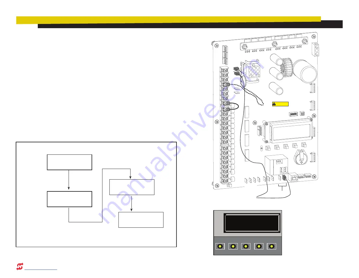
Status Display
GATE CLOSED
Installer Menu
R2 0 DISABLED
User Menu
CT 0 (OFF)
Installer Menu
R2 28 FLASH AC
Press MENU twice
at a Run Mode static
display.
To access the Installer Menu,
press and hold RESET & OPEN,
and then release them.
Press Next, until “R2 0 DISABLED” appears.
Press SELECT. The “R2”
characters blink.
Press Next until ““R2 28 FLASH AC” appears (Or
choose R2 “27” if you don’t want the lights to flash.)
Press SELECT again to set the User Relay 2 function.
RELAY 2: INSTALLER MENU FLOW DIAGRAM


