ENGLISH –
55
EN
3.5 PRE-INSTALLATION WORKS
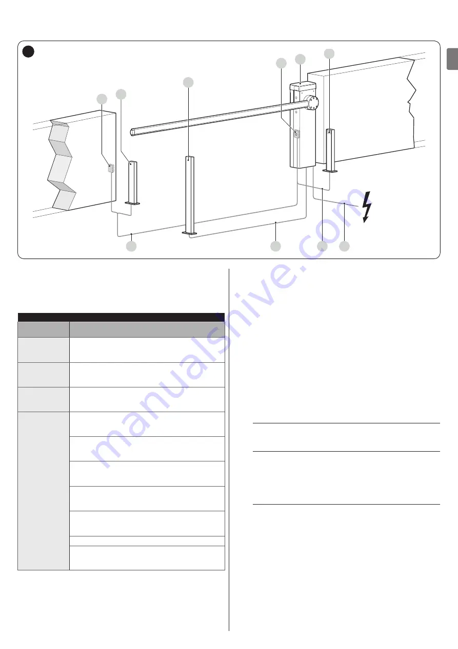
The figure shows an example of an automation system, constructed using
Nice
components.
A
B
C
2
3
2
1
A
D
B
5
A
Photocells
B
Photocells on column
C
Key selector
D
Boom gate cubicle
Table 3
TECHNICAL SPECIFICATIONS OF ELECTRICAL CABLES
Identification
no.
Cable characteristics
1
GEARMOTOR POWER SUPPLY cable
1 cable 3 x 1.5 mm
2
Maximum length 30 m [
note 1
]
2
BLUEBUS cable
1 cable 2 x 0.5 mm
2
Maximum length 20 m [
note 2
]
3
KEY SELECTOR cable
2 cables 2 x 0.25 mm
2
[
note 3
]
Maximum length 30 m
Other cables
OPEN INPUT cable
1 cable 2 x 0.25 mm
2
Maximum length 30 m
CLOSE INPUT cable
2 x 0.25 mm
2
Maximum length 30 m
WARNING LIGHT cable [
note 4
]
1 cable 2 x 0.5 mm
2
Maximum length 30 m
ANTENNA cable
1 x RG58-type shielded cable
Maximum length 15 m; recommended < 5 m
OPEN BOOM INDICATOR cable [
note 4
]
1 cable 2 x 0.5 mm
2
Maximum length 30 m
BOOM LIGHTS cable [
note 4
]
MASTER/SLAVE cable
1 cable 3 x 1 mm
2
Maximum length 20 m
These above-mentioned components are positioned according
to a typical standard layout. Using the layout in “
Figure
” as
a reference, define the approximate position in which each
component of the system will be installed.
Note 1
If the power supply cable is longer than 30 m, a cable
with larger cross-sectional area (3 x 2.5 mm
2
) must be
used and a safety earthing system must be installed
near the automation.
Note 2
If the BlueBus cable is longer then 20 m, up to maximum
40 m, it is necessary to use a cable with a greater cross-
sectional area (2 x 1 mm
2
).
Note 3
These two cables can be replaced by a single 4 x 0.5
mm
2
cable.
Note 4
Before making the connection, verify that the output is
programmed on the basis of the device to be connected
(refer to the chapter “
a
The cables used must be suited to the type of
environment of the installation site.
a
When laying the pipes for routing the electrical
cables, take into account that any water deposits in
the junction boxes may cause the connection pipes
to form condensate inside the control unit, thus
damaging the electronic circuits.
a
Before proceeding with the installation, prepare
the required electrical cables by referring to
“
Figure
” and to that stated in the “
Summary of Contents for L9BAR
Page 46: ...46 ITALIANO IT NOTE...
Page 95: ...ENGLISH 95 EN NOTES...
Page 144: ...144 FRAN AIS FR NOTES...
Page 193: ...ESPA OL 193 ES NOTAS...
Page 242: ...242 DEUTSCH DE ANMERKUNGEN...
Page 291: ...NEDERLANDS 291 NL OPMERKINGEN...
Page 340: ...340 POLSKI PL UWAGI...
Page 353: ...353 RU 3 7 a 1 15 2 16 3 4 4 5 17 1 0 15 0 2 3 0 25 0 8 2 0 9 4 12 400 1000 12 2 3 A m A B 18...
Page 354: ...354 RU 4 5 2 6 B 7 8 8 17 3 8 1 A A 19 2 B 3 B 20 m 4 C 6 C 21 5 D M BAR L BAR D D 22...
Page 355: ...355 RU 6 E E E 23 7 8 F G 1 F F F G G F F 24 9 H 10 I H I 25 11 J 12 6 J 26 l...
Page 357: ...357 RU 4 20 70 5 3 11 1 A 180 A A 30 2 1 A 2 1 A 180 2 U B 3 C A B C 31 4 5 U 6 A 7...
Page 358: ...358 RU 4 4 4 1 f a 1 A A 32 2 3 3 4 L N 33 5 34...
Page 363: ...363 RU 7 5 30 TX RX 41 8 20 50 9 EN 12445 10 200 20 1 11 6 2 a a a 1 2 42 42 3 4 5 6 l Nice...
Page 371: ...371 RU 1 1 24 10 2 2 24 10 3 3 24 10 4 4 24 10 24 10 OU4 xba7 24 0 5 0 5 Ogi OU4 xba8 2 1 3 2...
Page 384: ...384 RU 9 9 1 2 6 A A 57 3 4 B B 58 5 C STOP C C 59 6 7 a 60 8 LIGHT m LIGHT LIGHT 61...
Page 385: ...385 RU 9 62 10 6 63 9 10 XBA7 XBA8 Oview...
Page 386: ...386 RU 10 10 M L BAR a 1 6 20 000 2 3 4 5 11 11 l a l a...
Page 389: ...389 RU...
Page 390: ...390 RU a a a l 1 2 3 3 2 m m l 1...
Page 391: ...391 RU 1 A 180 A A 64 2 1 A 2 3 4 U 5 A 6...
Page 393: ...393 RU 22 ___ ___...
Page 394: ...394...
Page 395: ...395...


