


ENGLISH –
83
EN
9.2.1 BlueBUS
BlueBUS is a technique that allows for connecting compatible
devices with only two wires which carry the electrical power and
the communication signals. All devices are connected in parallel
on the same 2 BlueBUS wires and without having to observe the
polarities; each device is recognised because it is assigned a
univocal address during the installation phase.
The following devices can be connected to the BlueBUS:
photocells, safety devices, control buttons, signalling lights,
etc. The control unit recognises all the connected devices
individually through an appropriate learning phase, and can
detect all possible anomalies with absolute precision.
For this reason, whenever a device is connected to or removed
from BlueBUS, the learning phase must be carried out on the
control unit, as described in the “
”
paragraph.
9.2.2 STOP input
STOP is the input that causes immediate stoppage of the
manoeuvre followed by its brief reversal. Devices with output
featuring normally open “NO” and normally closed “NC”
contacts, as well as devices with 8.2 kΩ fixed resistor output,
such as sensitive edges, can be connected to this input.
As with the BlueBUS, the control unit recognises the type of
device connected to the STOP input during the learning phase
(see the “
” paragraph); subsequently
the control unit gives a STOP command when it detects a
variation with respect to the recognised status.
Multiple devices, even of different types, can be connected to
the STOP input if suitable arrangements are made:
–
Any number of NO devices can be connected to each other
in parallel.
–
Any number of NC devices can be connected to each other
in series.
–
Two devices with 8.2 kΩ fixed resistor output can be connected
in parallel; if there are more than 2 devices then they must all
be connected in cascade, with a single 8.2 kΩ terminating
resistor.
–
It is possible to combine two NO and NC contacts by placing
them in parallel, while also mounting a 8.2 kΩ resistor in series
with the NC contact (this also allows for combining 3 devices:
NA, NC and 8.2 kΩ).
a
If the STOP input is used to connect devices with
safety functions, only those devices with 8.2 kΩ
fixed resistor guarantee Category 3 safety against
faults in accordance with the EN 13849-1 standard.
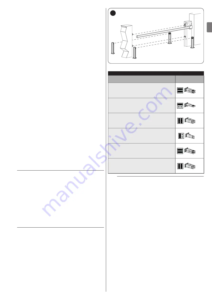
9.2.3 Photocells
To allow the control unit to recognise the devices connected
through the “BlueBUS” system, these devices must be
addressed.
This operation can be carried out by correctly positioning
the electrical jumper present in each device (also refer to
the instruction manual of each device). Shown below is an
addressing diagram for photocells, based on their type.
l
It is possible to connect two photocells to the
“Bluebus” input with the “FA1 open” and “FA2
open” command function (jumper A on the back
of the TX and RX boards must be cut). When these
photocells intervene, the control unit commands an
opening manoeuvre. For further information, refer
to the instruction manual for the photocells.
FA1
FA1
FA2
FA2
FOTO 1 II
FOTO 1 II
FOTO 1
FOTO 1
47
Table 16
PHOTOCELL ADDRESSES
Photocell
Position of the
jumpers
FOTO (PHOTO)
Photocell h = 50 activated during the
closing phase (stops and reverses the
gate’s movement)
FOTO II (PHOTO II)
Photocell h = 100 activated during the
closing phase (stops and reverses the
gate’s movement)
FOTO 1 (PHOTO 1)
External photocell h = 50 activated during
the closing phase (stops and reverses the
gate’s movement)
FOTO 1 II (PHOTO 1 II)
External photocell h = 100 activated
during the closing phase (stops and
reverses the gate’s movement)
FA1
Photocell for opening command
(cut jumper A on the back of the TX and
RX boards)
FA2
Photocell for opening command
(cut jumper A on the back of the TX and
RX boards)
m
At the end of the installation procedure, or after
photocells or other devices have been removed,
it is necessary to complete the learning procedure
” paragraph).
9.2.4 EDSP digital selector and proximity reader for ETPB
transponder cards
The “
Bluebus
” system allows for connecting up to four EDSP
digital selectors or four ETPB transponder card readers.
With EDSP it is possible to command the automation by entering
on the keyboard one of the memorised numerical combinations.
With ETPB it is possible to command the automation by simply
moving the memorised transponder card close to the sensor.
These devices are equipped with a unique code that it learned
and memorised by the control unit during the learning phase of
all the connected devices (see paragraph “
“).
This prevents any fraudulent attempt to replace a device and
any unauthorised person from commanding the automation.
For further information, consult the EDSP and ETPB instruction
manual.
Summary of Contents for L9BAR
Page 46: ...46 ITALIANO IT NOTE...
Page 95: ...ENGLISH 95 EN NOTES...
Page 144: ...144 FRAN AIS FR NOTES...
Page 193: ...ESPA OL 193 ES NOTAS...
Page 242: ...242 DEUTSCH DE ANMERKUNGEN...
Page 291: ...NEDERLANDS 291 NL OPMERKINGEN...
Page 340: ...340 POLSKI PL UWAGI...
Page 353: ...353 RU 3 7 a 1 15 2 16 3 4 4 5 17 1 0 15 0 2 3 0 25 0 8 2 0 9 4 12 400 1000 12 2 3 A m A B 18...
Page 354: ...354 RU 4 5 2 6 B 7 8 8 17 3 8 1 A A 19 2 B 3 B 20 m 4 C 6 C 21 5 D M BAR L BAR D D 22...
Page 355: ...355 RU 6 E E E 23 7 8 F G 1 F F F G G F F 24 9 H 10 I H I 25 11 J 12 6 J 26 l...
Page 357: ...357 RU 4 20 70 5 3 11 1 A 180 A A 30 2 1 A 2 1 A 180 2 U B 3 C A B C 31 4 5 U 6 A 7...
Page 358: ...358 RU 4 4 4 1 f a 1 A A 32 2 3 3 4 L N 33 5 34...
Page 363: ...363 RU 7 5 30 TX RX 41 8 20 50 9 EN 12445 10 200 20 1 11 6 2 a a a 1 2 42 42 3 4 5 6 l Nice...
Page 371: ...371 RU 1 1 24 10 2 2 24 10 3 3 24 10 4 4 24 10 24 10 OU4 xba7 24 0 5 0 5 Ogi OU4 xba8 2 1 3 2...
Page 384: ...384 RU 9 9 1 2 6 A A 57 3 4 B B 58 5 C STOP C C 59 6 7 a 60 8 LIGHT m LIGHT LIGHT 61...
Page 385: ...385 RU 9 62 10 6 63 9 10 XBA7 XBA8 Oview...
Page 386: ...386 RU 10 10 M L BAR a 1 6 20 000 2 3 4 5 11 11 l a l a...
Page 389: ...389 RU...
Page 390: ...390 RU a a a l 1 2 3 3 2 m m l 1...
Page 391: ...391 RU 1 A 180 A A 64 2 1 A 2 3 4 U 5 A 6...
Page 393: ...393 RU 22 ___ ___...
Page 394: ...394...
Page 395: ...395...


