


202
– DEUTSCH
DE
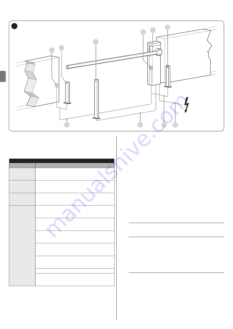
3.5 VORBEREITENDE ARBEITEN VOR DER INSTALLATION
Die Abbildung zeigt ein Beispiel für eine Automatisierungsanlage, die mit
Nice
-Komponenten realisiert wurde.
A
B
C
2
3
2
1
A
D
B
5
A
Fotozellen
B
Fotozellen auf Standsäule
C
Schlüsselschalter
D
Schrankenheber
Tabelle 3
TECHNISCHE EIGENSCHAFTEN DER STROMKABEL
Bezeichnung
Eigenschaften des Kabels
1
VERSORGUNGSKABEL GETRIEBEMOTOR
1 Kabel 3 x 1,5 mm
2
Maximale Länge 30 m [
Anmerkung 1
]
2
BLUEBUS-Kabel
1 Kabel 2 x 0,5 mm
2
Maximale Länge 20 m [
Anmerkung 2
]
3
Kabel SCHLÜSSELSCHALTER
2 Kabel 2 x 0,25 mm
2
[
Anmerkung 3
]
Maximale Länge 30 m
Andere Kabel
Kabel EINGANG OPEN
1 Kabel 2 x 0,25 mm
2
Maximale Länge 30 m
Kabel EINGANG CLOSE
2 x 0,25 mm
2
Maximale Länge 30 m
Kabel BLINKLEUCHTE [
Anmerkung 4
]
1 Kabel 2 x 0,5 mm
2
Maximale Länge 30 m
Kabel ANTENNE
1 abgeschirmtes Kabel vom Typ RG58
Maximale Länge 15 m; empfohlen < 5 m
Kabel LEUCHTE SCHRANKE OFFEN [
Anmerkung 4
]
1 Kabel 2 x 0,5 mm
2
Maximale Länge 30 m
Kabel SCHRANKENBAUM-LICHTER [
Anmerkung 4
]
Kabel MASTER/SLAVE
1 Kabel 3 x 1 mm
2
Maximale Länge 20 m
Die oben genannten Komponenten wurden nach einem
typischen und gebräuchlichen Schema positioniert. Mithilfe des
Beispiels von „
Abbildung
“ die ungefähre Position bestimmen,
in der die für die Anlage vorgesehenen Komponenten installiert
werden sollen.
Anmerkung 1
Wenn das Versorgungskabel länger als 30 m
ist, muss ein Kabel mit größerem Querschnitt benutzt
werden (3 x 2,5 mm
2
) und es ist eine Sicherheitserdung
in der Nähe der Automation erforderlich.
Anmerkung 2
Falls das BlueBus-Kabel länger als 20 ist (bis
maximal 40 m), muss ein Kabel mit einem größeren
Querschnitt verwendet werden (2 x 1 mm
2
).
Anmerkung 3
Diese zwei Kabel können durch ein einzelnes
Kabel mit 4 x 0,5 mm
2
ersetzt werden.
Anmerkung 4
Bevor der Anschluss hergestellt wird,
ist zu prüfen, ob der Ausgang entsprechend der
anzuschließenden Vorrichtung programmiert ist (siehe
Kapitel „
“).
a
Die verwendeten Kabel müssen der
Installationsumgebung gerecht werden.
a
Während der Rohrverlegung für den Durchgang
der Stromkabel ist zu berücksichtigen, dass
sich am Anschlusskabel, durch mögliche
Wasseransammlungen im Abzweigschacht,
Kondenswasser im Inneren der Steuerung bilden
kann und die Stromkreisläufe beschädigen werden
könnten.
a
Vor der Installation alle für die Anlage notwendigen
Stromkabel vorbereiten, siehe hierzu „Abbildung
5“ sowie die Angaben in Kapitel „TECHNISCHE
“.
Summary of Contents for L9BAR
Page 46: ...46 ITALIANO IT NOTE...
Page 95: ...ENGLISH 95 EN NOTES...
Page 144: ...144 FRAN AIS FR NOTES...
Page 193: ...ESPA OL 193 ES NOTAS...
Page 242: ...242 DEUTSCH DE ANMERKUNGEN...
Page 291: ...NEDERLANDS 291 NL OPMERKINGEN...
Page 340: ...340 POLSKI PL UWAGI...
Page 353: ...353 RU 3 7 a 1 15 2 16 3 4 4 5 17 1 0 15 0 2 3 0 25 0 8 2 0 9 4 12 400 1000 12 2 3 A m A B 18...
Page 354: ...354 RU 4 5 2 6 B 7 8 8 17 3 8 1 A A 19 2 B 3 B 20 m 4 C 6 C 21 5 D M BAR L BAR D D 22...
Page 355: ...355 RU 6 E E E 23 7 8 F G 1 F F F G G F F 24 9 H 10 I H I 25 11 J 12 6 J 26 l...
Page 357: ...357 RU 4 20 70 5 3 11 1 A 180 A A 30 2 1 A 2 1 A 180 2 U B 3 C A B C 31 4 5 U 6 A 7...
Page 358: ...358 RU 4 4 4 1 f a 1 A A 32 2 3 3 4 L N 33 5 34...
Page 363: ...363 RU 7 5 30 TX RX 41 8 20 50 9 EN 12445 10 200 20 1 11 6 2 a a a 1 2 42 42 3 4 5 6 l Nice...
Page 371: ...371 RU 1 1 24 10 2 2 24 10 3 3 24 10 4 4 24 10 24 10 OU4 xba7 24 0 5 0 5 Ogi OU4 xba8 2 1 3 2...
Page 384: ...384 RU 9 9 1 2 6 A A 57 3 4 B B 58 5 C STOP C C 59 6 7 a 60 8 LIGHT m LIGHT LIGHT 61...
Page 385: ...385 RU 9 62 10 6 63 9 10 XBA7 XBA8 Oview...
Page 386: ...386 RU 10 10 M L BAR a 1 6 20 000 2 3 4 5 11 11 l a l a...
Page 389: ...389 RU...
Page 390: ...390 RU a a a l 1 2 3 3 2 m m l 1...
Page 391: ...391 RU 1 A 180 A A 64 2 1 A 2 3 4 U 5 A 6...
Page 393: ...393 RU 22 ___ ___...
Page 394: ...394...
Page 395: ...395...


