88
– ENGLISH
EN
a
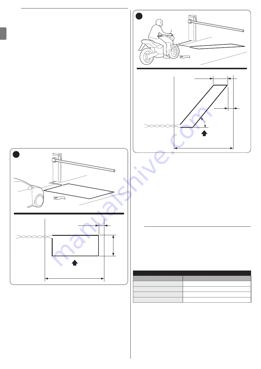
Precautions for making the loops:
–
install the loop close to the boom gate
–
the inductive loop's electric cables must be routed
separately from the other cables in the boom gate
circuit (power, accessories, etc.)
–
if the inductive loops are connected to different boom
gates, they must be located at least 1 m apart from
each other
–
the inductive loop must be installed in such a way as
to be unable to move, since any movement due to an
unstable surface can cause false positives (undesired
tripping)
–
the size of the loops must be defined based on the
application, bearing in mind that they must be located
at least 20 cm away from any fixed metal objects and 1
m away from any moving metal objects (“
Figure
To achieve the best result, we recommend using a loop
size no greater than that of the object to be detected
by the system
–
loops used to detect the passage of cars or trucks are
generally rectangular, and they must be located at 45°
with respect to the bicycle/motorcycle lane (“
Figure
”). We recommend cutting the corners of the floor
trace at 45° to avoid breaking the cable
–
to prevent interference, the loop cables must be
crossed at least 20 times per metre, and they should
not have joints; if you need to extend a cable, solder the
wires and seal them with heat-shrink sheathing
–
the twisted cable should be no longer than 20 m.
~ 0,35 m
SM
CR
1 m
53
SM
Direction of travel
CR
Traffic lane
~ 0,8 m
SM
CR
0,2 m
45°
54
SM
Direction of travel
CR
Traffic lane
Instructions for making the loops
Once you have defined the size of the loop:
1.
cut a trench in the floor; the trench should be 8 mm wide
and 30-50 mm deep (“
Figure
”)
2.
clean the trench and insert the coil, pushing it thoroughly
down so that it cannot move
3.
complete the number of turns of the loop required by
single-pole copper wire with a cross-section of 1.5 mm
2
(“
Figure
4.
cover the loop with sand to protect it and then seal the
trench with tar or outdoors flooring resin (“
Figure
a
Warning! – The sealant temperature may not
exceed the maximum temperature allowed for the
cable sheathing, otherwise the cable might not be
grounded correctly.
5.
first, connect the cables to the metal detector, and then
connect them from the metal detector to the Loop1 and
Loop2 terminals.
Table 20
POSITIONING THE LOOP
Perimeter of the loop
Number of turns
2 – 4 m
6
4 – 7 m
5
7 – 12 m
4
Greater than 12 m
3
Note
If there is any metal reinforcing bar under the floor, loop
induction is reduced. If so, run the loop twice more
around the perimeter.
Summary of Contents for L9BAR
Page 46: ...46 ITALIANO IT NOTE...
Page 95: ...ENGLISH 95 EN NOTES...
Page 144: ...144 FRAN AIS FR NOTES...
Page 193: ...ESPA OL 193 ES NOTAS...
Page 242: ...242 DEUTSCH DE ANMERKUNGEN...
Page 291: ...NEDERLANDS 291 NL OPMERKINGEN...
Page 340: ...340 POLSKI PL UWAGI...
Page 353: ...353 RU 3 7 a 1 15 2 16 3 4 4 5 17 1 0 15 0 2 3 0 25 0 8 2 0 9 4 12 400 1000 12 2 3 A m A B 18...
Page 354: ...354 RU 4 5 2 6 B 7 8 8 17 3 8 1 A A 19 2 B 3 B 20 m 4 C 6 C 21 5 D M BAR L BAR D D 22...
Page 355: ...355 RU 6 E E E 23 7 8 F G 1 F F F G G F F 24 9 H 10 I H I 25 11 J 12 6 J 26 l...
Page 357: ...357 RU 4 20 70 5 3 11 1 A 180 A A 30 2 1 A 2 1 A 180 2 U B 3 C A B C 31 4 5 U 6 A 7...
Page 358: ...358 RU 4 4 4 1 f a 1 A A 32 2 3 3 4 L N 33 5 34...
Page 363: ...363 RU 7 5 30 TX RX 41 8 20 50 9 EN 12445 10 200 20 1 11 6 2 a a a 1 2 42 42 3 4 5 6 l Nice...
Page 371: ...371 RU 1 1 24 10 2 2 24 10 3 3 24 10 4 4 24 10 24 10 OU4 xba7 24 0 5 0 5 Ogi OU4 xba8 2 1 3 2...
Page 384: ...384 RU 9 9 1 2 6 A A 57 3 4 B B 58 5 C STOP C C 59 6 7 a 60 8 LIGHT m LIGHT LIGHT 61...
Page 385: ...385 RU 9 62 10 6 63 9 10 XBA7 XBA8 Oview...
Page 386: ...386 RU 10 10 M L BAR a 1 6 20 000 2 3 4 5 11 11 l a l a...
Page 389: ...389 RU...
Page 390: ...390 RU a a a l 1 2 3 3 2 m m l 1...
Page 391: ...391 RU 1 A 180 A A 64 2 1 A 2 3 4 U 5 A 6...
Page 393: ...393 RU 22 ___ ___...
Page 394: ...394...
Page 395: ...395...


