


EN
English –
9
English –
9
These are the most important phases of automation set-up for ensuring maxi-
mum system safety. The test can also be performed as a periodic check of
automation devices. Testing and commissioning of the automation must be
performed by skilled and qualified personnel, who are responsible for the tests
required to verify the solutions adopted according to the risks present, and for
ensuring observance of all legal provisions, standards and regulations, and in
particular all requirements of the standard EN 12445, which establishes the test
methods for checking automations for doors and barriers. All these operations
must be performed under the direct supervision of the head installer, i.e. the
person who enters his/her name and signature in box N°1 of the declaration of
conformity (see appendix I).
The additional or optional devices must undergo a specific test for functionality
and correct interaction with the barrier.
5.1 - Testing
The sequence of operations to be performed for testing refers to a standard
system (
Fig. 1
) classed for “untrained users” and the automation activation set
to “automatic control” which envisages, as a minimum protection level of the
primary edge, device types C (force limitation - see standard EN 12445) com-
bined with device types D (presence detectors, e.g. photocells). Bearing in
mind that this type of use is among the most intensive, the same testing
sequence can be effectively implemented in less intensive conditions.
1
Ensure that all specifications in this manual have been observed, with spe-
cial reference to the chapter “1 Safety Instructions”.
2
Check correct balancing of the pole, see paragraph 3.8.
3
Check correct operation of the manual release, see paragraph 3.6.
4
Using the transmitter or key-operated selector switch, perform tests of
opening, closing and stopping the barrier, and ensure that pole movement
corresponds to specifications. Test several times to check for pole move-
ment and any defects in assembly or adjustment and any possible points of
friction.
5
Check operation of all system safety devices one at a time (photocells, sen-
sitive edges, etc.). Each time a device is activated the “Bluebus” LED on the
control unit must flash rapidly twice to confirm acknowledgement of the
event.
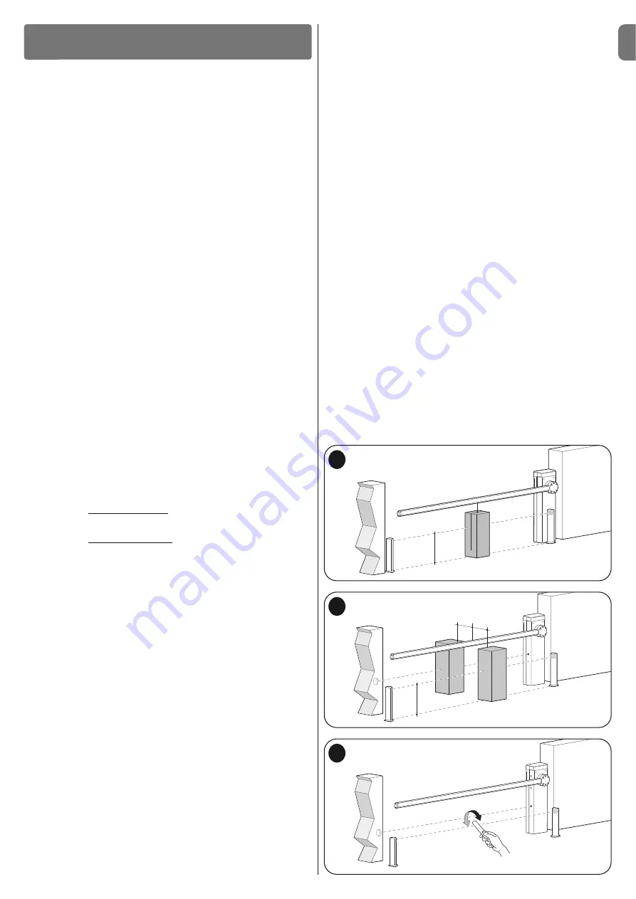
6
Check correct operation of the photocells as follows: depending on
whether one or two pairs of photocells have been installed, one or two par-
allelepipeds in rigid material are required (e.g. wooden panels) with the
measurements 70 x 30 x 20 cm. Each parallelepiped must have three
sides, one for each size, in reflective material (e.g. mirror or white gloss
paint) and three sides in opaque material (e.g. black matt paint). To test the
photocells positioned at 50 cm from the ground, the parallelepiped must be
placed on the ground or raised at 50 cm in the case of photocells placed at
1 m from the ground.
When testing one pair of photocells, the test specimen must be positioned
exactly at the centre of the pole with the 20 cm sides facing the photocells
and moved along the entire length of the pole (
Fig. A
).
When testing two pairs of photocells, the test must first be performed indi-
vidually for each pair of photocells, using one test specimen, and then
repeated using two test specimens.
Each test specimen must be positioned laterally with respect to the centre
of the pole, at a distance of 15 cm sides and then moved along the entire
length of the pole (
Fig. B
).
During these tests, the test specimen must be read by the photocells in any
position along the entire length of the pole.
7
Ensure there is no interference between the photocells and other devices,
by intercepting the optic axis joining the two photocells by means of a cylin-
der (diameter 5 cm, length 30 cm,
Fig. C
): pass the cylinder first close to
the TX photocell, then close to the RX and lastly at the centre between the
two. Ensure that in all cases the device engages, changing from the active
status to alarm status and vice versa, and that the envisaged action is gen-
erated in the control unit (for example movement inversion in the
Closing
manoeuvre).
8
Check protection against the risk of lifting:
on automations with verti-
cal movement, it must be ensured that there is no risk of lifting. This test can
be performed as follows: hang a weight of 20 kg mid-way along the pole
(for example, a sack of gravel), activate an Opening manoeuvre and ensure
that during operation the pole does not exceed the height of 50 cm from
the closing position. If the pole exceeds this height, reduce the motor force
(see chapter 6 - Table 7).
9
If hazardous situations generated by the moving poles are protected by
means of impact force limitation, measure the force as specified in the stan-
dard EN 12445. If motor force control is used as auxiliary function with the
system for reduction of impact force, test and identify the setting that
obtains the best results.
10 Check efficiency of the release system:
place the pole in the Closing
position and manually release the gearmotor (see paragraph 3.6) ensuring
that there is no difficulty with this procedure. Ensure that the manual force
required to move the pole on opening is no greater than 200 N (approx. 20
Kg); the force is measured perpendicular to the pole and at 1 m from the
rotation axis. Lastly, ensure that the key required for manual release is avail-
able in the vicinity of the automation.
11 Power supply disconnection system check:
by using the power dis-
connect device, and disconnecting any buffer batteries, ensure that all leds
on the control unit are off and that the pole remains stationary when any
commands are sent. Check efficiency of the locking device to prevent inad-
vertent and/or unauthorised reconnection.
5.2 - Commissioning
Commissioning can only be performed after positive results of all test
phases. Partial or “makeshift” commissioning is strictly prohibited.
1
Compile and provide the automation owner with the
“
CE Declaration of
conformity - Appendix I
”
, at the end of this manual, in the removable sec-
tion.
2
Compile and provide the automation owner with the form “
Operation
Manual
” at the end of this manual, in the removable section.
3
Compile the form “
Maintenance schedule
”
,
containing all maintenance
instructions for all devices in the automation and forward it to the owner. In
the case of the barrier, this form is present at the end of this manual, in the
removable section.
4
Before commissioning the automation, ensure that the owner is adequately
informed of all associated risks and hazards.
5
Permanently affix on the barrier, the label in the pack regarding the gearmo-
tor manual release and locking operations.
6
ONLY for installations NOT IN CONFORMITY with the criteria stated in
chapter 1.3.1 of this manual: produce the technical documentation of the
automation, which must include the following documents: an overall draw-
ing of the automation, the wiring diagram of all connections made, an
assessment of all risks present and relative solutions adopted (see forms to
be compiled on the website
www.niceforyou.com
), declarations of con-
formity of the manufacturer of all devices used (for the barrier see appendix
II) and the declaration of conformity compiled by the installer.
Affix a dataplate on the barrier, specifying at least the following data: type of
automation, name and address of manufacturer (responsible for commis-
sioning), serial number, year of construction and CE mark.
TESTING AND COMMISSIONING
5
300
200
700
500
A
300
200
700
300
200
700
500
150
150
B
C
Summary of Contents for M3BAR
Page 2: ......
Page 26: ......
Page 30: ...II 4 3 b a c d g h f e c a b...
Page 31: ...III 5 6 MBAR a c d b...
Page 32: ...IV 90 8 9 MBAR a b c a b 7 a b...
Page 33: ...V 180 10 11 LBAR c a a b...
Page 34: ...VI 13 14 12 LBAR c a b...
Page 35: ...VII 15 16 18 17...
Page 36: ...VIII 19 20 21 23 22...
Page 37: ...IX 24 26 25 28 1 cm 27 29...
Page 38: ...X 33 34 30 31 32 c a b c a b...
Page 39: ...XI 35 36 37 45 38 a b a b c...
Page 41: ...XIII 42 43 44 STOP 45 46 LIGHT 47...
Page 42: ...XIV 48 49 50 a b c...
Page 43: ...XV 51 52 a b...
Page 44: ...XVI 53 a b c d e f g...
Page 46: ...XVIII F1 F1 F2 F2 55...
Page 47: ......
Page 48: ...ISTML BARR01 4865_07 10 2011 www niceforyou com Nice SpA Oderzo TV Italia info niceforyou com...


