background image

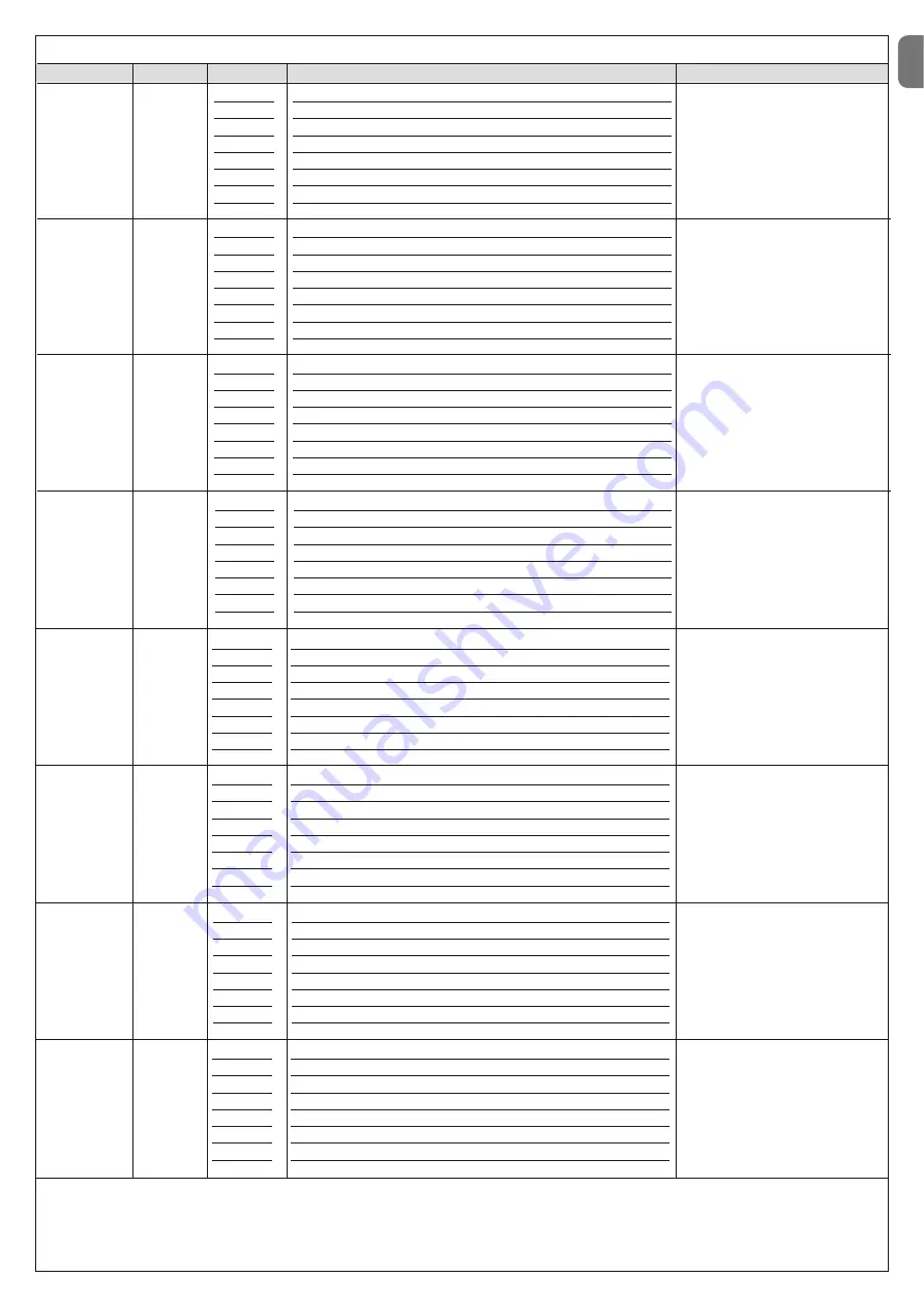
TABLE 8 - Second level functions

Input LED

Parameter

LED (level)

Value

Description

EN

English – 

11

L1

L1
L2
L3
L4
L5
L6
L7
L8

3 seconds
5 seconds
7 seconds
10 seconds
15 seconds
20 seconds
40 seconds
60 seconds

Sets the pause time, i.e. the time that
passes between the end of an ope-
ning manoeuvre and the start of an
automatic closing manoeuvre
This parameter is only effective if the
“automatic Closure” is active.

Time
Pause

L2

L1
L2
L3
L4
L5
L6
L7
L8

Open – stop – close - stop
Open – stop – close - open 
Open – close – open - close
Apartment block 1
Apartment block 2
Step by step 2 
Hold-to-run
Opening in semi-automatic mode, closing in dead man mode

Sets the sequence of commands as-
sociated with the input or the radio
control: “Step by step”.

Function
Step by
step

L3

L1
L2
L3
L4
L5
L6
L7
L8

Speed 1 (50%)
Speed 2 (80%)
Speed 3 (100%)
Open V3, Close V1
Open V1, Close V2
Open V2, Close V3
Open V3, Close V2
Open V2, Close V1

Sets the motor speed during normal
travel.

Speed
Motor

L4

L1
L2
L3
L4
L5
L6
L7
L8

Pole Open Indicator (24 V - 10 W)
Pole closed (24 V - 10 W)
Pole open (24 V - 10 W)
Flashing light(12 V - 21 W)
Flashing light 1 (24 V - 10 W) (for pole lights)
Electric lock(24 V - 10 W)
Suction cup(24 V - 10 W)
Maintenance indicator (24 V - 10 W)

Selects the type of device connected
to the LIGHT output.

Important!

– If the programmed set-

ting is modified, check the type of
voltage of the new device connected
to the LIGHT terminal and ensure that
it corresponds to the type of voltage
of the selected programming level.

1LIGHT
Output

WARNINGS:

– Do not set an excessively high value for the “motor force” as this may impair operation of the safety system or damage the pole; 
– If the “Motor force control” is used in support of the system for impact force reduction, after each adjustment the force measurement procedure must be performed, as envisaged
by standard EN 12445.
– Wear and atmospheric conditions influence movement of the pole; motor force settings should be checked periodically.

L8

L1
L2
L3
L4
L5
L6
L7
L8

0 - absent
1
2
3
5
6
8
9 - maximum

Set the intensity of the braking car-
ried out during the deceleration pha -
se of the manoeuvre.

Braking

L5

L1
L2
L3
L4
L5
L6
L7
L8

Flashing light (only during the manoeuvre)
Flashing light 1 (always flashing)
Courtesy light
Always lit
Red traffic light
Green traffic light
One-way traffic light
Two-way traffic light

Select the operating mode of the
device connected to the LED output.
Modes from L1 to L4 can be associ-
ated to the LED flashing light device.
Modes from L5 to L8 can be associ-
ated to the LED traffic light device.

Important! 

– Never connect devices

other than those specified.

Led Output

(cover lights)

L6

L1
L2
L3
L4
L5
L6
L7
L8

Force 1 (low)
Force 2
Force 3
Force 4
Force 5
Force 6
Force 7
Force 8 (high)

During the movement, adjust the
control system of the motor force to
adapt it to the weight of the pole.

Motor 
force

L7

L1
L2
L3
L4
L5
L6
L7
L8

100% - maximum
90%
80%
70%
60%
50%
40%
30% - minimum

Adjust the detection sensitivity of the
metal objects of the Loop Detector
circuit. See paragraph 7.5 - chap. 7
Further details.

Loop
Detector
Sensitivity

Summary of Contents for M3BAR

Page 1: ...ctions et avertissements pour l installation et l utilisation ES Instrucciones y advertencias para la instalaci n y el uso DE Installierungs und Gebrauchsanleitungen und Hinweise PL Instrukcje i ostrz...

Page 2: ......

Page 3: ...ngs On the power line to the system install a device for disconnection from the power mains with a gap between contacts that assures complete discon nection in the conditions of overvoltage category I...

Page 4: ...e S p a product catalogue The electromagnetic compatibility may not be guaranteed if the product is used in configurations or with other products that have not been foreseen the use of the product is...

Page 5: ...riers for residential and indus trial use they control the opening and closing of a road transit point with widths from 3 to 8 metres IMPORTANT All uses other than the intended use described and use i...

Page 6: ...aracteristics of electrical cables 3 3 1 Modifying the factory settings of the Closure manoeuvre If Closure to the right is required proceed as follows MBAR Version 01 Remove the cover fig 4 02 Loosen...

Page 7: ...ncy must be checked and ensure that the 4 anchoring points can resist a load of at least 1000 Kg For fixture use 12 MA screws 3 5 Pole installation 3 5 1 Pole support assembly 01 Insert the two plugs...

Page 8: ...fig 24 03 Insert the universal joint in the free ends of the two poles Take care in cor rectly directing the joint since the heads of the screws must be on the same part of the holes on the poles fig...

Page 9: ...output In the factory it is configured for operation with Pole Open Indicator 24 V 10 W BLUEBUS this terminal enables the connection of compatible devices all are connected in parallel with just two...

Page 10: ...rom the power mains and insert the receiver as shown in fig 42 Table 5 shows the actions performed by the control unit according to the out puts activated or the commands sent from the radio receiver...

Page 11: ...ing the optic axis joining the two photocells by means of a cylin der diameter 5 cm length 30 cm Fig C pass the cylinder first close to the TX photocell then close to the RX and lastly at the centre b...

Page 12: ...n Paragraph 4 5 EN 10 English The control unit has 3 keys OPEN STOP Set CLOSE Fig 49 that can be used both for controlling the unit during testing and for programming the available functions The progr...

Page 13: ...the type of voltage of the selected programming level 1LIGHT Output WARNINGS Do not set an excessively high value for the motor force as this may impair operation of the safety system or damage the p...

Page 14: ...he Set key for approx 3 seconds 02 Release the key when LED L1 starts flashing 03 Press the key or to move from the LED that is flashing to LED L4 LIGHT output input LED 04 Press and hold the Set key...

Page 15: ...ction opens FA1 and opens FA2 can be connected to the Bluebus input it is necessary to cut the A jumper at the rear of TX and RX cards When these photocells intervene the control unit commands an open...

Page 16: ...olution Off All OK CLOSE input not active On CLOSE input activation Normal if the device connected to the CLOSE input is active FC1 limit switch LED Cause Solution Off Limit switch activation If the p...

Page 17: ...n During normal operation indicates Stand BY active Flashes Programming of functions in progress If this flashes together with L3 this indicates that the device learning phase of the opening and closi...

Page 18: ...Loop activation time is the time t linked to the operating modes described in Table 16 Loop frequency display signals the fluctuation frequency of the loop selected in Hz 7 5 2 Installation WARNINGS...

Page 19: ...maximum temperature admitted for the isola tion of the cable otherwise a loss in isolation towards the earth may occur TABLE 15 Function Values Default Loop 1 sensitivity 10 100 90 Loop 2 sensitivity...

Page 20: ...it is possible to carry out the following connections its own flashing light Flash its own Pole Open Indicator S C A pole lights its own sensitive edge Stop its own command device P P which commands t...

Page 21: ...he event of illegal dis posal of this product The manoeuvre is performed but shortly afterwards the pole blocks or performs a brief inversion the selected force value may be too low to enable the move...

Page 22: ...output for signal indicator 24V max 10W Output for flashing light with optional accessories XBA7 LED flashing light or XBA8 LED traffic light traffic light on cover BLUEBUS output 1 output with maxim...

Page 23: ...cil of 21 December 1988 regarding the approximation of legislation regulations and administration of Member States concerning construction products according to the following harmonised standards EN 1...

Page 24: ...02 Radio spectrum art 3 2 EN 300 330 2 V1 5 1 2010 In accordance with directive 1999 5 CE annex V the product is classified as class 1 and marked DIRECTIVE 2004 108 EC OF THE EUROPEAN PARLIAMENT AND C...

Page 25: ...sh es and the manoeuvre is not started the number of flashes depends on the reason for which the manoeuvre does not start In this case the user must press and hold the command within three seconds Aft...

Page 26: ......

Page 27: ...he test procedure 10 Check protection against the risk of lifting on automations with vertical movement it must be ensured that there is no risk of lifting This test can be performed as follows hang a...

Page 28: ...lish Date Description of operation describe checks adjustments repairs modifications etc Signature of technician Signature of owner That all phases as envisaged in the maintenance schedule have been p...

Page 29: ...mm 464 5 mm 400 mm 1219 5 mm 900 mm M3BAR M5BAR M7BAR L Bar 298 5 mm 464 5 mm 500 mm 1219 5 mm 900 mm EN with joint IT con giunto FR avec raccord ES con uni n DE mit Gelenkverbindung PL ze z czk NL m...

Page 30: ...II 4 3 b a c d g h f e c a b...

Page 31: ...III 5 6 MBAR a c d b...

Page 32: ...IV 90 8 9 MBAR a b c a b 7 a b...

Page 33: ...V 180 10 11 LBAR c a a b...

Page 34: ...VI 13 14 12 LBAR c a b...

Page 35: ...VII 15 16 18 17...

Page 36: ...VIII 19 20 21 23 22...

Page 37: ...IX 24 26 25 28 1 cm 27 29...

Page 38: ...X 33 34 30 31 32 c a b c a b...

Page 39: ...XI 35 36 37 45 38 a b a b c...

Page 40: ...C NO NO C C MOTB MOFB OPEN CLOSE TX RX 24V 4W LIGHT FLASH SCA BLUEBUS STOP OPEN CLOSE P P LIGHT FLASH SCA BLUEBUS STOP OPEN CLOSE P P LOOP2 LOOP1 41 IN 1 IN 2 IN 3 LOOP 2 MASTER SLAVE LOOP 1 OUT 3 OUT...

Page 41: ...XIII 42 43 44 STOP 45 46 LIGHT 47...

Page 42: ...XIV 48 49 50 a b c...

Page 43: ...XV 51 52 a b...

Page 44: ...XVI 53 a b c d e f g...

Page 45: ...FLASH SCA MOTB OPEN CLOSE TX RX BLUEBUS STOP OPEN CLOSE P P 24V 4W BUS T4 M S LOOP2 LOOP1 LIGHT FLASH SCA BLUEBUS STOP OPEN CLOSE P P 24V 4W BUS T4 M S LOOP2 LOOP1 NC NC NO NO C C NC NC NO NO C C 54 M...

Page 46: ...XVIII F1 F1 F2 F2 55...

Page 47: ......

Page 48: ...ISTML BARR01 4865_07 10 2011 www niceforyou com Nice SpA Oderzo TV Italia info niceforyou com...

Reviews: