background image

EN

12

– English

7.1 - Total deletion of control unit memory

It is possible to delete all memorised data on the control unit and reset it to the
original factory settings:

01.

Press and hold down “

” and “

” keys at the same time;

02.

Release the keys when all Led illuminate (after approx.3 seconds);

03.

When leds 

L1

and 

L2

start flashing, this means that the procedure is ter-

minated.

Note – With this procedure it is also possible to delete any errors remaining in
the memory.

Important 

– This procedure does not delete the parameter regarding the

direction of motor rotation and the number of manoeuvres performed.

7.2 - Other functions

• “Always open” function

This function is a special feature of the control unit; it is associated with the
“Step Step” input and enables an “always open” command when the Step
Step command remains active for more than 3 seconds. This function is valid
for any setting of the Step Step input (see “SS Function” in 

Table 8

).

For example, it can be used to connect a clock for programming permanent
opening of the barrier during a specific time band.

• “Move anyway” function

If one or more safety devices malfunctions or is out of service, this function
enables control of the barrier in “hold-to-run” mode (for details, see chapter
“operation manual”).

FURTHER DETAILS

7

• “Maintenance notification” function

This function enables notification of when an automation maintenance check is
necessary. The “Maintenance notification” parameter can be set by using the
Oview programmer. The maintenance notification is signalled via the Flash
flashing light or by the maintenance indicator according to the type of setting.
The signals emitted by the Flash flashing light and the maintenance indicator
are shown in 

Table 10

.

• Check of number of manoeuvres performed

To check the number of manoeuvres performed, the Oview programmer is
required; parameters that can be checked under the item “Maintenance”.

• Manoeuvre counter reset

The manoeuvres can be reset at the end of the automation maintenance phase
and must be carried out by 

deactivating

the “Maintenance indicator” function

related to the LIGHT output.

Note - Temporarily disconnect the device connected to the 1 LIGHT
output.

Procedure to 

activate

 the Maintenance indicator (when 

it is not already

active

):

01.

Press and hold down the “

Set

”“ key for approx. 3 seconds;

02.

Release the key when LED “

L1

” starts flashing;

03.

Press the key “

” or “

” to move from the LED that is flashing to LED L4

(“LIGHT output” input LED);

04.

Press and hold the “

Set

” key through to completion of point 07;

05.

Wait approx. 3 seconds, until the LED of the programmed output illumi-
nates;

06.

Press keys “

” or “

” to move the lit LED on L8;

07.

Release the key “

Set

” and wait for the output for the timeout from the pro-

gramming procedure.

Procedure to 

deactivate

 the Maintenance indicator (when 

it is not already

active

):

01.

Press and hold down the “

Set

”“ key for approx. 3 seconds;

02.

Release the key when LED “

L1

” starts flashing;

03.

Press the key “

” or “

” to move from the LED that is flashing to LED L4

(“LIGHT output” input LED);

04.

Press and hold the “

Set

” key through to completion of point 07;

05.

Wait approx. 3 seconds, until LED L8 illuminates;

06.

Press keys “

” or “

” to move the lit LED on a LED other than L8;

07.

Release the key “

Set

” and wait for the output for the timeout from the pro-

gramming procedure.

Now the maintenance notification has been cancelled.

Note – Reset the programming of the LIGHT output with the device to be used
and then reconnect it to the output.

Open

Stop

Set

Close

L1

Close

Open

PP

Stop

Bluebus

2

L2

L3

L4

L5

L6

L7

L8

BusT4

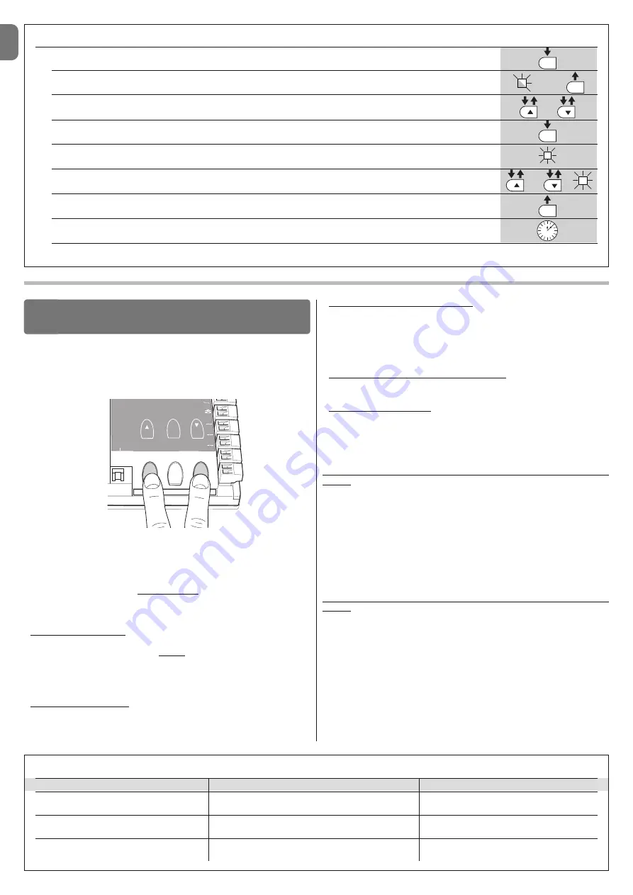
TABLE 9 - Programming procedure (second level functions)

01.

Press and hold down the “

Set

” key for approx. 3 seconds;

02.

Release the key when LED 

L1

starts flashing;

03.

Press keys “

” or “

” to move from the flashing led to the led associated with the function to be modified;

04.

Press and hold the “

Set

” key through to completion of point 06;

05.

Wait approx. 3 seconds, until the LED representing the current level of the parameter to be modified illuminates;

06.

Press keys 

or 

to move the LED representing the value of the parameter;

07.

Release the “

Set

” key;

08.

Wait 10 seconds (maximum time) to exit the programming mode.

Note

– During this procedure, points 03 to 07 need to be repeated when programming other parameters during the phase itself.

SET

SET

SET

SET

L1

or

or

3 s

10 s

TABLE 10

Number of manoeuvres

Flash flashing light

Maintenance indicator

Below 80% of the limit

Normal (0.5 sec. lit - 0.5 sec. off)

Light on for 2 seconds at the start of the 
opening manoeuvre.

Between 81% and 100% of the limit

Light on for 2 seconds at the start of the manoeuvre.

Flashing for entire duration of manoeuvre then 
continuing as normal

Over 100% of the limit

At the start and end of the manoeuvre, remains lit 

Always flashes

for 2 sec., then continues as normal.

Summary of Contents for M3BAR

Page 1: ...ctions et avertissements pour l installation et l utilisation ES Instrucciones y advertencias para la instalaci n y el uso DE Installierungs und Gebrauchsanleitungen und Hinweise PL Instrukcje i ostrz...

Page 2: ......

Page 3: ...ngs On the power line to the system install a device for disconnection from the power mains with a gap between contacts that assures complete discon nection in the conditions of overvoltage category I...

Page 4: ...e S p a product catalogue The electromagnetic compatibility may not be guaranteed if the product is used in configurations or with other products that have not been foreseen the use of the product is...

Page 5: ...riers for residential and indus trial use they control the opening and closing of a road transit point with widths from 3 to 8 metres IMPORTANT All uses other than the intended use described and use i...

Page 6: ...aracteristics of electrical cables 3 3 1 Modifying the factory settings of the Closure manoeuvre If Closure to the right is required proceed as follows MBAR Version 01 Remove the cover fig 4 02 Loosen...

Page 7: ...ncy must be checked and ensure that the 4 anchoring points can resist a load of at least 1000 Kg For fixture use 12 MA screws 3 5 Pole installation 3 5 1 Pole support assembly 01 Insert the two plugs...

Page 8: ...fig 24 03 Insert the universal joint in the free ends of the two poles Take care in cor rectly directing the joint since the heads of the screws must be on the same part of the holes on the poles fig...

Page 9: ...output In the factory it is configured for operation with Pole Open Indicator 24 V 10 W BLUEBUS this terminal enables the connection of compatible devices all are connected in parallel with just two...

Page 10: ...rom the power mains and insert the receiver as shown in fig 42 Table 5 shows the actions performed by the control unit according to the out puts activated or the commands sent from the radio receiver...

Page 11: ...ing the optic axis joining the two photocells by means of a cylin der diameter 5 cm length 30 cm Fig C pass the cylinder first close to the TX photocell then close to the RX and lastly at the centre b...

Page 12: ...n Paragraph 4 5 EN 10 English The control unit has 3 keys OPEN STOP Set CLOSE Fig 49 that can be used both for controlling the unit during testing and for programming the available functions The progr...

Page 13: ...the type of voltage of the selected programming level 1LIGHT Output WARNINGS Do not set an excessively high value for the motor force as this may impair operation of the safety system or damage the p...

Page 14: ...he Set key for approx 3 seconds 02 Release the key when LED L1 starts flashing 03 Press the key or to move from the LED that is flashing to LED L4 LIGHT output input LED 04 Press and hold the Set key...

Page 15: ...ction opens FA1 and opens FA2 can be connected to the Bluebus input it is necessary to cut the A jumper at the rear of TX and RX cards When these photocells intervene the control unit commands an open...

Page 16: ...olution Off All OK CLOSE input not active On CLOSE input activation Normal if the device connected to the CLOSE input is active FC1 limit switch LED Cause Solution Off Limit switch activation If the p...

Page 17: ...n During normal operation indicates Stand BY active Flashes Programming of functions in progress If this flashes together with L3 this indicates that the device learning phase of the opening and closi...

Page 18: ...Loop activation time is the time t linked to the operating modes described in Table 16 Loop frequency display signals the fluctuation frequency of the loop selected in Hz 7 5 2 Installation WARNINGS...

Page 19: ...maximum temperature admitted for the isola tion of the cable otherwise a loss in isolation towards the earth may occur TABLE 15 Function Values Default Loop 1 sensitivity 10 100 90 Loop 2 sensitivity...

Page 20: ...it is possible to carry out the following connections its own flashing light Flash its own Pole Open Indicator S C A pole lights its own sensitive edge Stop its own command device P P which commands t...

Page 21: ...he event of illegal dis posal of this product The manoeuvre is performed but shortly afterwards the pole blocks or performs a brief inversion the selected force value may be too low to enable the move...

Page 22: ...output for signal indicator 24V max 10W Output for flashing light with optional accessories XBA7 LED flashing light or XBA8 LED traffic light traffic light on cover BLUEBUS output 1 output with maxim...

Page 23: ...cil of 21 December 1988 regarding the approximation of legislation regulations and administration of Member States concerning construction products according to the following harmonised standards EN 1...

Page 24: ...02 Radio spectrum art 3 2 EN 300 330 2 V1 5 1 2010 In accordance with directive 1999 5 CE annex V the product is classified as class 1 and marked DIRECTIVE 2004 108 EC OF THE EUROPEAN PARLIAMENT AND C...

Page 25: ...sh es and the manoeuvre is not started the number of flashes depends on the reason for which the manoeuvre does not start In this case the user must press and hold the command within three seconds Aft...

Page 26: ......

Page 27: ...he test procedure 10 Check protection against the risk of lifting on automations with vertical movement it must be ensured that there is no risk of lifting This test can be performed as follows hang a...

Page 28: ...lish Date Description of operation describe checks adjustments repairs modifications etc Signature of technician Signature of owner That all phases as envisaged in the maintenance schedule have been p...

Page 29: ...mm 464 5 mm 400 mm 1219 5 mm 900 mm M3BAR M5BAR M7BAR L Bar 298 5 mm 464 5 mm 500 mm 1219 5 mm 900 mm EN with joint IT con giunto FR avec raccord ES con uni n DE mit Gelenkverbindung PL ze z czk NL m...

Page 30: ...II 4 3 b a c d g h f e c a b...

Page 31: ...III 5 6 MBAR a c d b...

Page 32: ...IV 90 8 9 MBAR a b c a b 7 a b...

Page 33: ...V 180 10 11 LBAR c a a b...

Page 34: ...VI 13 14 12 LBAR c a b...

Page 35: ...VII 15 16 18 17...

Page 36: ...VIII 19 20 21 23 22...

Page 37: ...IX 24 26 25 28 1 cm 27 29...

Page 38: ...X 33 34 30 31 32 c a b c a b...

Page 39: ...XI 35 36 37 45 38 a b a b c...

Page 40: ...C NO NO C C MOTB MOFB OPEN CLOSE TX RX 24V 4W LIGHT FLASH SCA BLUEBUS STOP OPEN CLOSE P P LIGHT FLASH SCA BLUEBUS STOP OPEN CLOSE P P LOOP2 LOOP1 41 IN 1 IN 2 IN 3 LOOP 2 MASTER SLAVE LOOP 1 OUT 3 OUT...

Page 41: ...XIII 42 43 44 STOP 45 46 LIGHT 47...

Page 42: ...XIV 48 49 50 a b c...

Page 43: ...XV 51 52 a b...

Page 44: ...XVI 53 a b c d e f g...

Page 45: ...FLASH SCA MOTB OPEN CLOSE TX RX BLUEBUS STOP OPEN CLOSE P P 24V 4W BUS T4 M S LOOP2 LOOP1 LIGHT FLASH SCA BLUEBUS STOP OPEN CLOSE P P 24V 4W BUS T4 M S LOOP2 LOOP1 NC NC NO NO C C NC NC NO NO C C 54 M...

Page 46: ...XVIII F1 F1 F2 F2 55...

Page 47: ......

Page 48: ...ISTML BARR01 4865_07 10 2011 www niceforyou com Nice SpA Oderzo TV Italia info niceforyou com...

Reviews:

Related manuals for M3BAR