


EN
English –
13
7.3 - Adding or removing devices
New devices can be added at any time, connected to the BlueBus and Stop
input or those present can be deleted as required. To do this, proceed as fol-
lows:
01.
Press and hold down “
▲
” and “
Set
” keys at the same time;
02.
Release the buttons when LEDs
L1
and
L2
start flashing very quickly (after
approx. 3 s);
03.
Wait a few seconds for the control unit to finish connected device self-
learning;
04.
At the end of this phase, the
STOP
LED must remain lit, while LEDs
L1
and
L2
turn off (where relevant LEDs L3 and L4 start flashing).
After performing this procedure, the automation testing procedure must be per-
formed as described in chapter 5.1.
7.3.1 - Bluebus Inlet
This Bluebus system allows device connections to be made using just 2 con-
ductors for both the electricity supply and the communication signals. All
devices are connected in parallel on the same 2 Bluebus wires, without the
need to observe polarity. Each device is individually recognized because a
unique address is assigned to it during installation. Bluebus can be used to
connect the following: photocells, safety devices, control devices such as key-
boards and readers for transponder cards, indicator lamps, etc. The control
unit recognises each one of the devices connected during the self-learning
phase and is able to detect all possible faults in maximum safety. For this rea-
son each time a device is connected to or removed from Bluebus the self-
learning phase must be repeated, as described in paragraph 4.4.
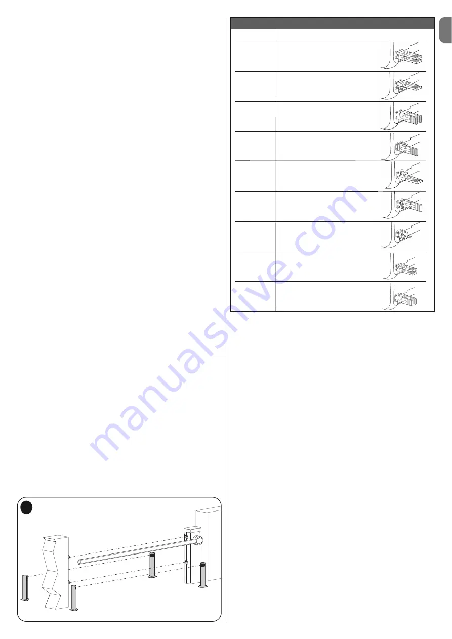
7.3.2 - Photocells
The Bluebus system enables the control unit to recognise the photocells, con-
trol routing of the relative jumpers (see
Table 11
) and enables assignment of
the correct value for the obstacle detection function. The routing operation is
performed both on TX and RX, positioning the jumpers in the same way with a
check that there are no pairs of photocells with the same address.
The photocells may be installed as shown in
fig. D
.
Important
– After installing
or removing the photocells, the device learning phase must be performed, as
described in paragraph 4.4.
It is possible to install the TX or RX photocell inside the caisson of the barrier, in
the space provided (
fig. 53
).
To install the photocell, proceed as follows:
01.
Extract the board of the photocell from its box by prizing it out with a slot-
ted tip screwdriver (
fig. 53-a
).
IMPORTANT!
- Do not damage the electric
components inside;
02.
Open the box prepared for the photocells, present in the accessory box
(
fig. 53-b
);
03.
Block the board on the bottom of the box (
fig. 53-c
);
04.
Pierce the rubber arranged for the passage of the electric cable (
fig. 53-d
);
05.
Route the electric cable and connect it to the terminal of the photocell (
fig.
53-e
);
06.
Close the bottom of the box with the cover, taking care to block the rubber
in its seat (
fig. 53-f
);
07.
Hook the box on the lens on the side of the caisson by making it slide from
top to bottom (
fig. 53-g
).
NOTE
– 2 photocells with control function “opens FA1” and “opens FA2” can
be connected to the Bluebus input (it is necessary to cut the A jumper at the
rear of TX and RX cards). When these photocells intervene, the control unit
commands an opening manoeuvre. For further information, refer to the instruc-
tion manual for the photocells.
7.3.3 - MOTB digital selector and proximity reader for MOMB
transponder cards
The Bluebus system enables connection of up to 4 MOTB digital selectors or 4
MOMB transponder badge readers.
MOTB enables control of the automation, by entering one of the memorised
numerical codes on the keypad.
MOMB enables control of the automation by simply placing the memorised
transponder bade close to the automation.
These devices have an individual code, which is recognised and memorised by
the control unit during the phase for learning all connected devices (see para-
graph 4.4).
This prevents an fraudulent attempts to replace a device or use of the automa-
tion by unauthorised persons. For further information, refer to the instruction
manual for MOTB and MOMB.
7.3.4 - STOP Input
The Stop input causes the manoeuvre to stop immediately followed by a short
reverse run. Devices with normally open NO or normally closed NC contact
outputs, optical devices (Opto Sensors), or devices with 8.2 k
Ω
constant resist-
ance output such as sensitive edges can be connected to this input. The con-
trol unit, during the learning phase, recognises the type of device connected
and activates a STOP command when any variation in the learnt status occurs.
When set accordingly, more than one device can be connected to the STOP
input, also different from one another;
• Several NO devices can be connected in parallel, with no limit to the number;
• Several NO devices can be connected in series, with no limit to the number;
• Two devices with an 8.2k
Ω
constant resistance output can be connected in
parallel; multiple devices must be connected “in cascade” with a single
8.2k
Ω
termination resistance;
• An NO and NC type combination is also possible, placing the 2 contacts in
parallel. In this case, a 8.2 k
Ω
resistance must be placed in series with the NC
contact; this also enables the combination of 3 devices: NO, NC and 8.2 k
Ω
.
Caution
– If the STOP input is used to connect devices with safety functions,
only the devices with a constant resistance of 8.2 k
Ω
or OPTO SENSOR opti-
cal devices guarantee adequate safety levels against faults.
For connection of an optical device type OPTO SENSOR make the connec-
tions as shown in
fig. E
. The maximum current provided on the 12 Vdc line is
40 mA.
TABLE 11 - PHOTOCELL ADDRESSES
Photocell
Jumpers
PHOTO
Photocell h = 50
activated on closure
PHOTO II
Photocell h = 100
activated on closure
PHOTO 1
Photocell h = 50
activated on closure
PHOTO 1 II
Photocell h = 100
activated on closure
PHOTO 2
Photocell activated on opening
(inverts on closing)
PHOTO 2 II
Photocell activated on opening
(inverts on closing)
PHOTO 3
Single photocell activated on
opening and closing
FA1
Photocell for opening command
(cut the A jumper at the read
of TX and RX cards)
FA2
Photocell for opening command
(cut the A jumper at the read
of TX and RX cards)
FA1
FA1
FA2
FA2
F 1 II
F 1 II
F 1
F 1
D
Summary of Contents for M3BAR
Page 2: ......
Page 26: ......
Page 30: ...II 4 3 b a c d g h f e c a b...
Page 31: ...III 5 6 MBAR a c d b...
Page 32: ...IV 90 8 9 MBAR a b c a b 7 a b...
Page 33: ...V 180 10 11 LBAR c a a b...
Page 34: ...VI 13 14 12 LBAR c a b...
Page 35: ...VII 15 16 18 17...
Page 36: ...VIII 19 20 21 23 22...
Page 37: ...IX 24 26 25 28 1 cm 27 29...
Page 38: ...X 33 34 30 31 32 c a b c a b...
Page 39: ...XI 35 36 37 45 38 a b a b c...
Page 41: ...XIII 42 43 44 STOP 45 46 LIGHT 47...
Page 42: ...XIV 48 49 50 a b c...
Page 43: ...XV 51 52 a b...
Page 44: ...XVI 53 a b c d e f g...
Page 46: ...XVIII F1 F1 F2 F2 55...
Page 47: ......
Page 48: ...ISTML BARR01 4865_07 10 2011 www niceforyou com Nice SpA Oderzo TV Italia info niceforyou com...


