background image

TABLE 17

Perimeter of the loop

Number of turns to be carried out

2 – 4 m

6

4 – 7 m

5

7 – 12 m

4

more than 12 m

3

Note

– If in the loop positioning place, below the floor, there are some metal

reinforcements, the inductivity of the loop is reduced. In this case, it is
necessary to add 2 turns to the twisting of the cable

EN

English – 

17

able sheath. 

The length of the twisted cable must be less than 20 m

.

01.

After determining the size of the loop, dig a groove in the floor of a width =
8 mm and a depth = 30-50 mm (

fig. H

);

02.

Clean the groove and insert the loop, trying to compact it in a way to avoid
it moving;

03.

Carry out the number of turns of the loop depending on the perimeter, as
indicated in 

Table 17

: use a 1.5 mm

unipolar isolated copper cable (

fig. H

);

04.

Before sealing the groove, check that the value of the inductive loop is
between 100 and 400 uH or, through the Oview programmer, check that
the value of the measured frequency (Parameter “Loop Frequency”) is
between 30 and100 KHz;

05.

Cover the loop with sand to protect it and then seal the groove with bitu-
men or resin for outdoor use (

fig. H

). 

Important!

– The temperature of the

sealant must not exceed the maximum temperature admitted for the isola-
tion of the cable, otherwise a loss in isolation towards the earth may occur.
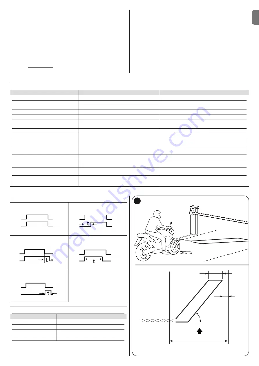
TABLE 15

Function

Values

Default

Loop 1 sensitivity

10 – 100%

90%

Loop 2 sensitivity

10 – 100%

90%

Loop power supply

on – off

on

Loop 1 active

on – off

on

Loop 2 active

on – off

on

Loop 1 operating mode

1 – 5

1

Loop 2 operating mode

1 – 5

1

Loop 1 permanence time

2 – 20 = always

20 = always

Loop 2 permanence time

2 – 20 = always

20 = always

Output function 1, 2, 3:
Active out (1,2,3) for loop 1

selectable

off

Output function 1, 2, 3:
Active out (1,2,3) for loop 2

selectable

off

Calibration [also carried out upon start-up]

on – off

Loop 1 activation mode*:

1 – 5

1

Loop 1 time

0 – 25 s

2s

Loop 2 activation mode*:

1 – 5

1

Loop 2 time

0 – 25 s

2s

Loop 1 frequency display

0 - 127000

-

Loop 2 frequency display

0 - 127000

-

G

approximately 0,8 m

Direction of travel

0,2 m

Route

45°

06.

The electric cables must be connected to the 

Loop1 

(

fig. I

) and 

Loop2

(

fig. L

) terminals. The Loop2 terminal presents 2 connection possibilities

(

fig. L

); based on the type of connection used, it varies the working fre-

quency of the loop.

Important!

– If Loop1 is positioned near Loop2 and both work at the

same frequency (or almost), interference could be generated; in this case,
it is necessary to change the connection to Loop2 terminal.

TABLE 16

1

loop

relay

loop

relay

loop

relay

loop

relay

loop

relay

2

3

4

5

Summary of Contents for M3BAR

Page 1: ...ctions et avertissements pour l installation et l utilisation ES Instrucciones y advertencias para la instalaci n y el uso DE Installierungs und Gebrauchsanleitungen und Hinweise PL Instrukcje i ostrz...

Page 2: ......

Page 3: ...ngs On the power line to the system install a device for disconnection from the power mains with a gap between contacts that assures complete discon nection in the conditions of overvoltage category I...

Page 4: ...e S p a product catalogue The electromagnetic compatibility may not be guaranteed if the product is used in configurations or with other products that have not been foreseen the use of the product is...

Page 5: ...riers for residential and indus trial use they control the opening and closing of a road transit point with widths from 3 to 8 metres IMPORTANT All uses other than the intended use described and use i...

Page 6: ...aracteristics of electrical cables 3 3 1 Modifying the factory settings of the Closure manoeuvre If Closure to the right is required proceed as follows MBAR Version 01 Remove the cover fig 4 02 Loosen...

Page 7: ...ncy must be checked and ensure that the 4 anchoring points can resist a load of at least 1000 Kg For fixture use 12 MA screws 3 5 Pole installation 3 5 1 Pole support assembly 01 Insert the two plugs...

Page 8: ...fig 24 03 Insert the universal joint in the free ends of the two poles Take care in cor rectly directing the joint since the heads of the screws must be on the same part of the holes on the poles fig...

Page 9: ...output In the factory it is configured for operation with Pole Open Indicator 24 V 10 W BLUEBUS this terminal enables the connection of compatible devices all are connected in parallel with just two...

Page 10: ...rom the power mains and insert the receiver as shown in fig 42 Table 5 shows the actions performed by the control unit according to the out puts activated or the commands sent from the radio receiver...

Page 11: ...ing the optic axis joining the two photocells by means of a cylin der diameter 5 cm length 30 cm Fig C pass the cylinder first close to the TX photocell then close to the RX and lastly at the centre b...

Page 12: ...n Paragraph 4 5 EN 10 English The control unit has 3 keys OPEN STOP Set CLOSE Fig 49 that can be used both for controlling the unit during testing and for programming the available functions The progr...

Page 13: ...the type of voltage of the selected programming level 1LIGHT Output WARNINGS Do not set an excessively high value for the motor force as this may impair operation of the safety system or damage the p...

Page 14: ...he Set key for approx 3 seconds 02 Release the key when LED L1 starts flashing 03 Press the key or to move from the LED that is flashing to LED L4 LIGHT output input LED 04 Press and hold the Set key...

Page 15: ...ction opens FA1 and opens FA2 can be connected to the Bluebus input it is necessary to cut the A jumper at the rear of TX and RX cards When these photocells intervene the control unit commands an open...

Page 16: ...olution Off All OK CLOSE input not active On CLOSE input activation Normal if the device connected to the CLOSE input is active FC1 limit switch LED Cause Solution Off Limit switch activation If the p...

Page 17: ...n During normal operation indicates Stand BY active Flashes Programming of functions in progress If this flashes together with L3 this indicates that the device learning phase of the opening and closi...

Page 18: ...Loop activation time is the time t linked to the operating modes described in Table 16 Loop frequency display signals the fluctuation frequency of the loop selected in Hz 7 5 2 Installation WARNINGS...

Page 19: ...maximum temperature admitted for the isola tion of the cable otherwise a loss in isolation towards the earth may occur TABLE 15 Function Values Default Loop 1 sensitivity 10 100 90 Loop 2 sensitivity...

Page 20: ...it is possible to carry out the following connections its own flashing light Flash its own Pole Open Indicator S C A pole lights its own sensitive edge Stop its own command device P P which commands t...

Page 21: ...he event of illegal dis posal of this product The manoeuvre is performed but shortly afterwards the pole blocks or performs a brief inversion the selected force value may be too low to enable the move...

Page 22: ...output for signal indicator 24V max 10W Output for flashing light with optional accessories XBA7 LED flashing light or XBA8 LED traffic light traffic light on cover BLUEBUS output 1 output with maxim...

Page 23: ...cil of 21 December 1988 regarding the approximation of legislation regulations and administration of Member States concerning construction products according to the following harmonised standards EN 1...

Page 24: ...02 Radio spectrum art 3 2 EN 300 330 2 V1 5 1 2010 In accordance with directive 1999 5 CE annex V the product is classified as class 1 and marked DIRECTIVE 2004 108 EC OF THE EUROPEAN PARLIAMENT AND C...

Page 25: ...sh es and the manoeuvre is not started the number of flashes depends on the reason for which the manoeuvre does not start In this case the user must press and hold the command within three seconds Aft...

Page 26: ......

Page 27: ...he test procedure 10 Check protection against the risk of lifting on automations with vertical movement it must be ensured that there is no risk of lifting This test can be performed as follows hang a...

Page 28: ...lish Date Description of operation describe checks adjustments repairs modifications etc Signature of technician Signature of owner That all phases as envisaged in the maintenance schedule have been p...

Page 29: ...mm 464 5 mm 400 mm 1219 5 mm 900 mm M3BAR M5BAR M7BAR L Bar 298 5 mm 464 5 mm 500 mm 1219 5 mm 900 mm EN with joint IT con giunto FR avec raccord ES con uni n DE mit Gelenkverbindung PL ze z czk NL m...

Page 30: ...II 4 3 b a c d g h f e c a b...

Page 31: ...III 5 6 MBAR a c d b...

Page 32: ...IV 90 8 9 MBAR a b c a b 7 a b...

Page 33: ...V 180 10 11 LBAR c a a b...

Page 34: ...VI 13 14 12 LBAR c a b...

Page 35: ...VII 15 16 18 17...

Page 36: ...VIII 19 20 21 23 22...

Page 37: ...IX 24 26 25 28 1 cm 27 29...

Page 38: ...X 33 34 30 31 32 c a b c a b...

Page 39: ...XI 35 36 37 45 38 a b a b c...

Page 40: ...C NO NO C C MOTB MOFB OPEN CLOSE TX RX 24V 4W LIGHT FLASH SCA BLUEBUS STOP OPEN CLOSE P P LIGHT FLASH SCA BLUEBUS STOP OPEN CLOSE P P LOOP2 LOOP1 41 IN 1 IN 2 IN 3 LOOP 2 MASTER SLAVE LOOP 1 OUT 3 OUT...

Page 41: ...XIII 42 43 44 STOP 45 46 LIGHT 47...

Page 42: ...XIV 48 49 50 a b c...

Page 43: ...XV 51 52 a b...

Page 44: ...XVI 53 a b c d e f g...

Page 45: ...FLASH SCA MOTB OPEN CLOSE TX RX BLUEBUS STOP OPEN CLOSE P P 24V 4W BUS T4 M S LOOP2 LOOP1 LIGHT FLASH SCA BLUEBUS STOP OPEN CLOSE P P 24V 4W BUS T4 M S LOOP2 LOOP1 NC NC NO NO C C NC NC NO NO C C 54 M...

Page 46: ...XVIII F1 F1 F2 F2 55...

Page 47: ......

Page 48: ...ISTML BARR01 4865_07 10 2011 www niceforyou com Nice SpA Oderzo TV Italia info niceforyou com...

Reviews:

Related manuals for M3BAR