


EN
English –
19
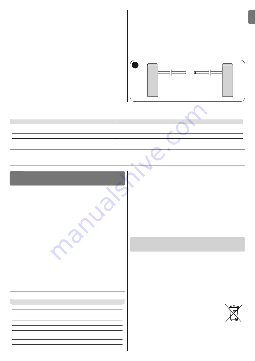
04.
Once all the electrical connections are done, power each control unit and
for each one, follow the procedure described in paragraph 4.2 -
Initial
start-up and electrical connections.
Important! – Should the Oview programmer be used, it is necessary to
modify the parameter “Together” or “Address” of one of the 2 control
units of the barrier; this is to avoid that the 2 control units communicate
with Oview at the same time.
05.
In the
Slave barrier
, carry out the following programming:
a)
Recognition of the connected devices (see paragraph 4.4)
b)
Recognition of opening and closing positions (see paragraph 4.5)
c)
Carry out any adjustments
d)
Activate the “Slave Mode” parameter as described in paragraph 6.1 -
Level one programming (ON-OFF).
At this point, LED
L7
starts flashing to signal a “Master-Slave communica-
tion error”. This is because the coupling of the Master barrier with the Slave
barrier has not yet been carried out.
Important!
- In the counterposed barrier, before carrying out “the opening
and closing learning phase”,
it is necessary to set the “Direction of
motor rotation”
(parameter L8 - Table 7, paragraph 6.1);
Important
– Consider that during operation, any programming on the Slave
barrier is ignored, since the programming on the Master barrier prevails,
excluding that reported in
Table 18
, which only affects the Slave barrier.
06.
In the
Master barrier
, carry out the following programming:
a)
Recognition of the connected devices (see paragraph 4.4)
b)
Recognition of opening and closing positions (see paragraph 4.5)
c)
carry out any adjustments;
07.
Finally,
from the Master control unit
, send a command to carry out a
manoeuvre and check that the latter is also carried out by the Slave barrier.
TABLE 18
Level one functions (ON-OFF functions)
Level two functions (adjustable parameters)
Stand-by Motor
Speed
Start-up Flash
Output
Slave Mode
LED output
Long/short deceleration
Motor force
Direction of motor rotation
Braking
PRODUCT DISPOSAL
This product is an integral part of the automation system it controls
and must be disposed of along with it.
As in the case of installation, likewise at the end of product lifetime the disas-
sembly and scrapping operations must be performed by qualified personnel.
This product is made of various types of material, some of which can be recy-
cled while others must be scrapped. Seek information on the recycling and dis-
posal methods envisaged by the local regulations in your area for this product
category.
Caution!
– Some parts of the product may contain polluting or hazardous sub-
stances which, if released to the environment, may cause serious damage to
the environment or to human health.
As indicated by the symbol alongside, disposal of this prod-
uct with domestic waste is strictly prohibited. Separate the
waste into categories for disposal, according to the methods
established by current legislation in your area, or return the
product to the retailer when purchasing a new version.
Caution!
– Local legislation may impose heavy fines in the event of illegal dis-
posal of this product.
•
The manoeuvre is performed, but shortly afterwards the pole blocks
or performs a brief inversion:
the selected force value may be too low to
enable the movement of the pole. Check the correct balancing of the pole; if
necessary set a higher force value.
The sensitivity value could be too high:
lower the sensitivity value. If the activation takes place in the deceleration
phase, it is necessary to decrease the braking intensity.
•
The manoeuvre is carried out at slow speed:
the manoeuvre does not
start from one of the limit switches or the control unit does not recognise the
limit switch. Check the electrical connection of the limit switch.
•
The Slave barrier does not perform the manoeuvres:
check that the
“Master-Slave” learning phase has been carried out on both the barriers.
•
The manoeuvre is carried out in the opposite way:
check that the
parameter “Direction of motor rotation” (parameter L8 - Table 7, paragraph 6.1)
is set correctly, or invert the motor cables.
Possible causes of malfunctions are listed below, which may occur during the
installation phase, or in the case of faults, possible remedies:
• The radio transmitter does not control the barrier and the transmitter
LED does not illuminate:
Check that the transmitter batteries are not dis-
charged and replace if necessary.
•
The radio transmitter does not control the barrier but the transmitter
LED illuminates:
check that the transmitter is correctly memorised on the
radio receiver. Ensure correct emission of the radio signal of the transmitter with
the following empirical test: Press a key and place the LED against the aerial of
a standard radio switched on and tuned to FM at the frequency of 108.5Mhz or
as close to this value as possible; a slight noise with a scratching pulse noise
should be heard.
• No manoeuvre is performed when a command is sent, and the OK
LED does not flash:
check that the barrier is powered via the mains at 230 V.
Also check that the fuses F1 and F2 are not blown; in this case try to locate the
cause of the fault and then replace with a version with the same specifications;
see
fig. 55
.
• No manoeuvre is performed when a command is sent, and the flash-
ing light remains off:
check that the command is effectively received; if the
sent command reaches the SS input, the OK LED emits a double flash to indi-
cate that the command is received.
• The manoeuvre does not start and the courtesy light flashes a few ti -
mes:
count the number of flashes and check against the data in
Table 19
.
WHAT TO DO IF…
(troubleshooting guide)
8
TABLE 19
Diagnostics with programming led
L1 fast flash:
device memory error
L2 fast flash:
position memory error
L3 fast flash:
parameter memory error
L4 fast flash:
flashing short circuit or courtesy light
L5 fast flash:
encoder counting error
L6 fast flash:
inverted limit switch error or limit switch not freed by the
set time
L7 fast flash:
Master/Slave communication error
L8 fast flash:
version error
M
Note
– Should you decide to use the “total standby” function in the barriers with the Master-Slave configuration, it is necessary to carry out the electrical connec-
tion using the BusT4 connector and
not the Master-Slave connector.
Summary of Contents for M3BAR
Page 2: ......
Page 26: ......
Page 30: ...II 4 3 b a c d g h f e c a b...
Page 31: ...III 5 6 MBAR a c d b...
Page 32: ...IV 90 8 9 MBAR a b c a b 7 a b...
Page 33: ...V 180 10 11 LBAR c a a b...
Page 34: ...VI 13 14 12 LBAR c a b...
Page 35: ...VII 15 16 18 17...
Page 36: ...VIII 19 20 21 23 22...
Page 37: ...IX 24 26 25 28 1 cm 27 29...
Page 38: ...X 33 34 30 31 32 c a b c a b...
Page 39: ...XI 35 36 37 45 38 a b a b c...
Page 41: ...XIII 42 43 44 STOP 45 46 LIGHT 47...
Page 42: ...XIV 48 49 50 a b c...
Page 43: ...XV 51 52 a b...
Page 44: ...XVI 53 a b c d e f g...
Page 46: ...XVIII F1 F1 F2 F2 55...
Page 47: ......
Page 48: ...ISTML BARR01 4865_07 10 2011 www niceforyou com Nice SpA Oderzo TV Italia info niceforyou com...


