background image

EN

English – 

A

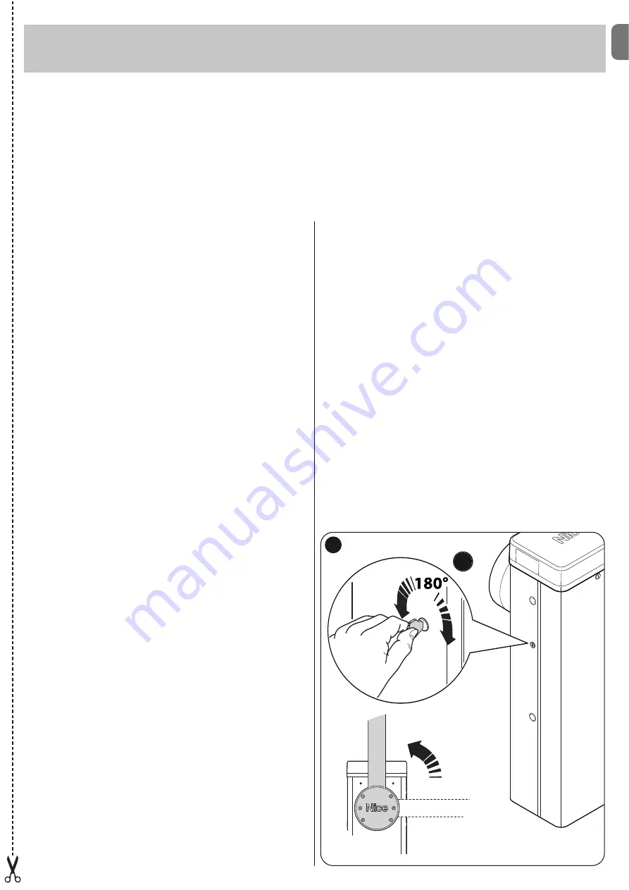
IMPORTANT! – The gearmotor release and locking operations
must be performed only when the pole is horizontal and sta-
tionary.

To manually lock and release the barrier, insert the key supplied and
turn it by 180° (

fig. A

); the key can be turned to the left or to the right.

Operation manual

(to be given to the final user of MBAR and LBAR)

Warnings

1 - Children:

An automation system guarantees a high level of safety,

using its detection systems to prevent movement in the presence of
persons or objects, and ensuring constantly foreseeable and safe acti-
vation. Nonetheless, it is advisable to ensure that children do not play
in the vicinity of the automation. This is not a toy!

2 - 

This product is not designed to be used by persons (including chil-

dren) whose physical, sensorial or mental capacities are reduced, or
with lack of experience or skill, unless suitable instructions regarding
use of the product have been provided by a person responsible for
safety or under supervision of the latter.

3 - Malfunctions

: if the automation is seen to perform abnormally,

disconnect the electrical power supply from the system and manually
release the gearmotor. Never attempt to perform repairs; contact your
local installer for assistance. In the meantime the system can be used
as a manual access point, after releasing the gearmotor as described
be low in this document.

In the event of breakage or a power fail-

ure

, while waiting for the installer or the electrical power supply to

return, if the buffer battery is not fitted, the automation can still be
used. Manually release the gearmotor (see step 9 - Gearmotor manu-
al releasing and locking) and move the pole manually as required.

4 - Safety devices disabled:

the barrier can be operated even when

the safety device on the barrier does not work correctly:

- Activate the barrier command (with the transmitter or key-operated

selector switch, etc.); if all is in working order, the pole opens or
closes normally; otherwise the flashing light emits a number of flash-
es and the manoeuvre is not started (the number of flashes depends
on the reason for which the manoeuvre does not start).

- In this case, the user must press and hold the command within three

seconds.

- After approx. 2 seconds the barrier will start to operate in “hold-to-

run” mode, i.e. the pole will continue to move while the command is
activated; THE POLE STOPS AS SOON AS THE COMMAND IS
RELEASED.

If the safety devices are out of service, the automation must be
repaired as soon as possible.

5 - 

Even if you possess the skills, never modify the system or pro-

gramming and setting parameters of the automation: this is the
responsibility of the installer.

6 - 

Testing, periodic maintenance and any repairs must be document-

ed by the person performing the operations and the relevant docu-
ments must be kept by the system owner. The only operations that
can be performed by the user periodically are to clean the photocell
lenses and the automation. To prevent anyone from activating the bar-
rier, release the automation system before proceeding with the opera-
tions (as described below). Use a slightly damp cloth to clean.

7 - Disposal

: At the end of the automation’s lifetime, ensure that it is

disposed by qualified personnel and that the materials are recycled or
scrapped according to current local standards.

8 - Gearmotor manual release and locking

: The gearmotor is

equipped with a mechanical system that enables manual opening and
closing of the pole. These operations are required in the event of a
power failure or malfunctions.

Before using the automation for the first time, ask the installer to explain the origin of residual risks and devote a few minutes to reading this user
instruction and warning manual given to you by the installer. Keep the manual for reference when in doubt and pass it on to new owners of the
automation.

IMPORTANT! – Your automation is a machine that performs your commands faithfully; negligent or improper use may constitute
a hazard:
– Never activate automation controls if persons, animals or objects are present in the operating range.
– Never touch parts of the automation while the pole is moving!
– Transit is only permitted if the pole is completely open and stationary!

A

a

Summary of Contents for M3BAR

Page 1: ...ctions et avertissements pour l installation et l utilisation ES Instrucciones y advertencias para la instalaci n y el uso DE Installierungs und Gebrauchsanleitungen und Hinweise PL Instrukcje i ostrz...

Page 2: ......

Page 3: ...ngs On the power line to the system install a device for disconnection from the power mains with a gap between contacts that assures complete discon nection in the conditions of overvoltage category I...

Page 4: ...e S p a product catalogue The electromagnetic compatibility may not be guaranteed if the product is used in configurations or with other products that have not been foreseen the use of the product is...

Page 5: ...riers for residential and indus trial use they control the opening and closing of a road transit point with widths from 3 to 8 metres IMPORTANT All uses other than the intended use described and use i...

Page 6: ...aracteristics of electrical cables 3 3 1 Modifying the factory settings of the Closure manoeuvre If Closure to the right is required proceed as follows MBAR Version 01 Remove the cover fig 4 02 Loosen...

Page 7: ...ncy must be checked and ensure that the 4 anchoring points can resist a load of at least 1000 Kg For fixture use 12 MA screws 3 5 Pole installation 3 5 1 Pole support assembly 01 Insert the two plugs...

Page 8: ...fig 24 03 Insert the universal joint in the free ends of the two poles Take care in cor rectly directing the joint since the heads of the screws must be on the same part of the holes on the poles fig...

Page 9: ...output In the factory it is configured for operation with Pole Open Indicator 24 V 10 W BLUEBUS this terminal enables the connection of compatible devices all are connected in parallel with just two...

Page 10: ...rom the power mains and insert the receiver as shown in fig 42 Table 5 shows the actions performed by the control unit according to the out puts activated or the commands sent from the radio receiver...

Page 11: ...ing the optic axis joining the two photocells by means of a cylin der diameter 5 cm length 30 cm Fig C pass the cylinder first close to the TX photocell then close to the RX and lastly at the centre b...

Page 12: ...n Paragraph 4 5 EN 10 English The control unit has 3 keys OPEN STOP Set CLOSE Fig 49 that can be used both for controlling the unit during testing and for programming the available functions The progr...

Page 13: ...the type of voltage of the selected programming level 1LIGHT Output WARNINGS Do not set an excessively high value for the motor force as this may impair operation of the safety system or damage the p...

Page 14: ...he Set key for approx 3 seconds 02 Release the key when LED L1 starts flashing 03 Press the key or to move from the LED that is flashing to LED L4 LIGHT output input LED 04 Press and hold the Set key...

Page 15: ...ction opens FA1 and opens FA2 can be connected to the Bluebus input it is necessary to cut the A jumper at the rear of TX and RX cards When these photocells intervene the control unit commands an open...

Page 16: ...olution Off All OK CLOSE input not active On CLOSE input activation Normal if the device connected to the CLOSE input is active FC1 limit switch LED Cause Solution Off Limit switch activation If the p...

Page 17: ...n During normal operation indicates Stand BY active Flashes Programming of functions in progress If this flashes together with L3 this indicates that the device learning phase of the opening and closi...

Page 18: ...Loop activation time is the time t linked to the operating modes described in Table 16 Loop frequency display signals the fluctuation frequency of the loop selected in Hz 7 5 2 Installation WARNINGS...

Page 19: ...maximum temperature admitted for the isola tion of the cable otherwise a loss in isolation towards the earth may occur TABLE 15 Function Values Default Loop 1 sensitivity 10 100 90 Loop 2 sensitivity...

Page 20: ...it is possible to carry out the following connections its own flashing light Flash its own Pole Open Indicator S C A pole lights its own sensitive edge Stop its own command device P P which commands t...

Page 21: ...he event of illegal dis posal of this product The manoeuvre is performed but shortly afterwards the pole blocks or performs a brief inversion the selected force value may be too low to enable the move...

Page 22: ...output for signal indicator 24V max 10W Output for flashing light with optional accessories XBA7 LED flashing light or XBA8 LED traffic light traffic light on cover BLUEBUS output 1 output with maxim...

Page 23: ...cil of 21 December 1988 regarding the approximation of legislation regulations and administration of Member States concerning construction products according to the following harmonised standards EN 1...

Page 24: ...02 Radio spectrum art 3 2 EN 300 330 2 V1 5 1 2010 In accordance with directive 1999 5 CE annex V the product is classified as class 1 and marked DIRECTIVE 2004 108 EC OF THE EUROPEAN PARLIAMENT AND C...

Page 25: ...sh es and the manoeuvre is not started the number of flashes depends on the reason for which the manoeuvre does not start In this case the user must press and hold the command within three seconds Aft...

Page 26: ......

Page 27: ...he test procedure 10 Check protection against the risk of lifting on automations with vertical movement it must be ensured that there is no risk of lifting This test can be performed as follows hang a...

Page 28: ...lish Date Description of operation describe checks adjustments repairs modifications etc Signature of technician Signature of owner That all phases as envisaged in the maintenance schedule have been p...

Page 29: ...mm 464 5 mm 400 mm 1219 5 mm 900 mm M3BAR M5BAR M7BAR L Bar 298 5 mm 464 5 mm 500 mm 1219 5 mm 900 mm EN with joint IT con giunto FR avec raccord ES con uni n DE mit Gelenkverbindung PL ze z czk NL m...

Page 30: ...II 4 3 b a c d g h f e c a b...

Page 31: ...III 5 6 MBAR a c d b...

Page 32: ...IV 90 8 9 MBAR a b c a b 7 a b...

Page 33: ...V 180 10 11 LBAR c a a b...

Page 34: ...VI 13 14 12 LBAR c a b...

Page 35: ...VII 15 16 18 17...

Page 36: ...VIII 19 20 21 23 22...

Page 37: ...IX 24 26 25 28 1 cm 27 29...

Page 38: ...X 33 34 30 31 32 c a b c a b...

Page 39: ...XI 35 36 37 45 38 a b a b c...

Page 40: ...C NO NO C C MOTB MOFB OPEN CLOSE TX RX 24V 4W LIGHT FLASH SCA BLUEBUS STOP OPEN CLOSE P P LIGHT FLASH SCA BLUEBUS STOP OPEN CLOSE P P LOOP2 LOOP1 41 IN 1 IN 2 IN 3 LOOP 2 MASTER SLAVE LOOP 1 OUT 3 OUT...

Page 41: ...XIII 42 43 44 STOP 45 46 LIGHT 47...

Page 42: ...XIV 48 49 50 a b c...

Page 43: ...XV 51 52 a b...

Page 44: ...XVI 53 a b c d e f g...

Page 45: ...FLASH SCA MOTB OPEN CLOSE TX RX BLUEBUS STOP OPEN CLOSE P P 24V 4W BUS T4 M S LOOP2 LOOP1 LIGHT FLASH SCA BLUEBUS STOP OPEN CLOSE P P 24V 4W BUS T4 M S LOOP2 LOOP1 NC NC NO NO C C NC NC NO NO C C 54 M...

Page 46: ...XVIII F1 F1 F2 F2 55...

Page 47: ......

Page 48: ...ISTML BARR01 4865_07 10 2011 www niceforyou com Nice SpA Oderzo TV Italia info niceforyou com...

Reviews:

Related manuals for M3BAR