


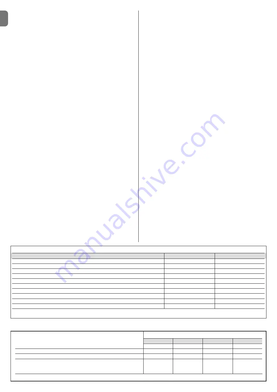
TABLE 1 - Essential requirements for CE marking (according to prospect ZA.1 of standard EN 13241-1)
Essential requirements
Point of standard
Result
Resistance to water
4.4.2
NPD
*
Release of hazardous substances
4.2.9
Compliant
Resistance to wind load
4.4.3
Compliant
Heat resistance
4.4.5
NPD
*
Permeability to air
4.4.6
NPD
*
Safe opening for vertically moving doors
4.2.8
Compliant
Definition of the geometry of glass components
4.2.5
NPD
*
Mechanical strength and stability
4.2.3
Compliant
Manoeuvring forces for power-operated doors/gates
4.3.3
Compliant
Durability of resistance to water, heat resistance and permeability to air
4.4.7
NPD
*
*
NPD = No Performance declared, when the product does not offer this performance, for example “Permeability to air”, or when the requirement is not applicable, such as “Definition
of the geometry of glass components”.
2
– English
EN
rier may not meet all the essential requirements.
The use of the product is
prohibited in these situations until the correspondence to the require-
ments of the directive has been verified by those performing the
installation
; in this case the “EC declaration of Conformity: appendix I” may
not be used. As a consequence, the installer in turn becomes the manufac-
turer of the “automatic barrier”, and must therefore observe all requirements
of the Machinery Directive 2006/42/EC. The manufacturer must complete a
risk assessment, which also includes the list of essential safety requirements
as stated in “appendix I of the Machinery Directive”, specifying the relative
solutions adopted. Note that the risk assessment is one of the documents
that constitutes the automation “technical documentation”. This must be
compiled by a professional installer with the possibility of using the “Declara-
tion of Conformity” in appendix II to be compiled by the installer of the road
barrier.
Special warnings regarding suitability of this product in relation to the
“Machinery” Directive 2006/42/CE; to be taken into consideration when
the installer becomes the manufacturer of the product
.
The road barrier is issued onto the market as a “quasi machine” and therefore
constructed for incorporation in a machine or to be assembled with other
machinery to produce a single “machine” in accordance with the Directive
2006/42/EC only in conjunction with the other components and in the ways as
described in this instruction manual. As established in directive 2006/42/EC,
this product may not be started up until the manufacturer of the machine, in
which this product is incorporated, has not identified and declared as compli-
ant with the directive 2006/42/EC.
• “Low Voltage” Directive:
Particular warnings concerning the suitable use of this product in relation to
the 2006/95/EEC “Low Voltage” Directive:
This product meets the requirements of the “Low Voltage” Directive if used as
specified in the configurations as envisaged in this instruction manual and in
combination with the articles listed in the product catalogue of Nice S.p.a.
These requirements may not be guaranteed if the product is used in configu-
rations or with other products that have not been foreseen; the use of the
product is prohibited in these situations until the correspondence to the
requirements foreseen by the directive have been verified by those perform-
ing the installation.
• “Electromagnetic compatibility” Directive:
Particular warnings concerning the suitable use of this product in relation to
the 2004/108/EEC “Electromagnetic Compatibility” 2004/10/EEC:
This product has been subjected to tests regarding the electromagnetic
compatibility in the most critical of use conditions, in the configurations fore-
seen in this instructions manual and in combination with articles present in
the Nice S.p.a. product catalogue..
The electromagnetic compatibility may not be guaranteed if the product is
used in configurations or with other products that have not been foreseen;
the use of the product is prohibited in these situations until the correspon-
dence to the requirements foreseen by the directive have been verified by
those performing the installation.
1.3.1 - Installation criteria and special warnings related to essential
requirements
This product, if correctly installed, complies with the essential requirements as
envisaged by the European Directive on “Construction Products” 89/106/EEC
according to the provisions of harmonised standard EN 13241-1, as specified
in
Table 1
; and by the European Directive on “Machinery” 2006/42/EC.
Important!
– If the road barrier is intended exclusively for vehicle transit, it
would be excluded from the field of application of EN 13241-1; in this case,
compliance with some of the requirements stated in Table 1 may not be com-
pulsory. Transit may be considered “exclusively vehicle” when there is an
express prohibition for other types (for example pedestrians), such as by using
adequate signs and, if other types are required, there is adequate space in the
immediate vicinity.
• Release of hazardous substances:
The product does not contain and/or release hazardous substances in con-
formity with the provisions of the standard EN 13241-1, point 4.2.9 and ac -
cording to the list of substances stated in the web site of the European Com-
munity *: http:// europa.eu.int/comm/enterprise/construction/internal/dangsub/
dangmain_en.htm
(
*
) Last update: 17/03/2003
Special warning to guarantee compliance with the requirement
– It is
essential that also all other materials used in installation, such as electric
cables, comply with this requirement
• Resistance to wind load:
Table 1a
specifies resistance of the pole supplied to the differential pressure of
the wind. The tests were performed with the pole fitted with the impact protec-
tion profile; other accessories may increase the exposed surface and thus
reduce the resistance to wind load.
• Safe opening for vertically moving doors:
The product does not cause uncontrolled movements or dropping of the pole
in the event of a fault on a single component of the suspension or balancing
(spring) system.
Special warnings to guarantee compliance with the requirements:
- Perform installation in strict observance of all instructions in chapters “
3 -
Installation
“ and “
5 - Testing and Commissioning
”.
- Ensure that a maintenance schedule is drawn up (for example, by using a
“Maintenance indicator” connected to the FLASH output associated with the
relative function - see Table 10); in which, all instructions in the chapter “Main-
tenance Schedule” must be strictly followed.
• Mechanical strength and stability of the product:
The product is designed and constructed to ensure that, during normal use, all
forces applied, impact and normal wear will not damage or impair mechanical
performance.
Caution:
See specifications for the requirement “Safe opening for vertically
moving doors”.
• Manoeuvring forces for power-operated doors/gates:
The operating forces applied by the pole in relation to the risks of crushing and
impact are protected by means of one of the three following methods:
1 For operation with “hold-to-run” controls:
as specified in EN 12453:
2000, point 5.1.1.4. In this case the control button must be located in sight of
the automation, and if accessible by the public, the control must not be avail-
able to the latter, for example protected by means of a key-operated selector
switch.
2 For “semi-automatic” operating mode:
by force limitation as specified in
EN 12453:2000, points 5.1.1.5 and 5.1.3.3.
TABLE 1a
Barrier
M3BAR
M5BAR
M7BAR
LBAR
Class
4
4
2
2*
Wind load [Pa]
≤ 1000
≤ 1000
≤ 450
≤ 450
Maximum wind speed [Km/h]
155
155
104
104
Descriptive term
Hurricane
Hurricane
Violent storm
Violent storm
Squall
Squall
*
Class 2 is achieved using accessory model WA11
Summary of Contents for M3BAR
Page 2: ......
Page 26: ......
Page 30: ...II 4 3 b a c d g h f e c a b...
Page 31: ...III 5 6 MBAR a c d b...
Page 32: ...IV 90 8 9 MBAR a b c a b 7 a b...
Page 33: ...V 180 10 11 LBAR c a a b...
Page 34: ...VI 13 14 12 LBAR c a b...
Page 35: ...VII 15 16 18 17...
Page 36: ...VIII 19 20 21 23 22...
Page 37: ...IX 24 26 25 28 1 cm 27 29...
Page 38: ...X 33 34 30 31 32 c a b c a b...
Page 39: ...XI 35 36 37 45 38 a b a b c...
Page 41: ...XIII 42 43 44 STOP 45 46 LIGHT 47...
Page 42: ...XIV 48 49 50 a b c...
Page 43: ...XV 51 52 a b...
Page 44: ...XVI 53 a b c d e f g...
Page 46: ...XVIII F1 F1 F2 F2 55...
Page 47: ......
Page 48: ...ISTML BARR01 4865_07 10 2011 www niceforyou com Nice SpA Oderzo TV Italia info niceforyou com...


