background image

English – 

5

EN

3.4 - Barrier lift fixture

3.4.1 - If the support surface already exists

01.

Open the cabinet of the barrier (

fig. 13

);

02.

Place the barrier on the fixing surface and trace the points where the slots
are to be fixed (

fig. 14

);

03.

Move the barrier and drill the traced surface points; then insert 4 expansion
bolts, not supplied (

fig. 15

);

04.

Position the barrier correctly and secure by means of the relative nuts and
washers not supplied (

fig. 16

).

3.4.2 - If the support surface does not exist

01.

Dig the foundation pit (

*

) to house the foundation plate;

02.

Prepare ducting for connection cables (

fig. 17

);

03.

On the foundation plate, fix the 4 bolts, placing a nut on the upper side of
each and one on the lower side of the plate (

fig. 17

). 

Caution

– The lower

nut must be tightened down to the threaded section;

04.

Now cast the concrete, and before it sets, embed the foundation plate,
which must be positioned flush with the surface, parallel to the pole and
perfectly level (

fig. 17

). Wait for the concrete to set completely; in general,

at least 2 weeks;

05.

Remove the 4 upper nuts of the bolts;

06.

Open the cabinet of the barrier (

fig. 18

);

07.

Position the barrier correctly and secure it by means of the relative nuts
and washers supplied with the foundation plate and removed in point 04
(

fig. 19

).

(

*

) Note - The fixing surface must be perfectly smooth and flat. If the surface is

in concrete, it must be at least 0.15 m thick, and must be adequately reinforced
with steel cages. The concrete volume must be greater than 0.2 m

3

(a thick-

ness of 0.25 m corresponds to 0.8 m

2

; in other words equal to a square base

of approx. 0.9 m per side). Anchoring to the concrete can be by means of 4
expansion bolts, fitted with 12 MA screws, which resist to a traction load of at
least 400 Kg. If the fixing surface is in another material, the consistency must be
checked and ensure that the 4 anchoring points can resist a load of at least
1000 Kg. For fixture, use 12 MA screws.

3.5 - Pole installation

3.5.1 - Pole support assembly

01.

Insert the two plugs in the relative seats on the output motor shaft (

fig. 20

);

02.

Position the support on the output motor shaft, placing it in the “vertical
pole” position and tighten the relative screws and washers fully down to
secure (

fig. 21

);

03.

Position the pole cover and partially secure by means of the 6 screws sup-
plied (

fig. 22

).

3.5.2 - Pole assembly (3 metres / 5 metres)

01.

Assemble the two pole insertions (

fig. 23

);

02.

Insert, from the same end of the pole, the insertions just assembled. Use a
rubber mallet (

fig. 24

);

03.

Lightly grease the aluminium guide on both sides (

fig. 25

);

08.

Perform this operation on both ends of the pole: insert the first part of impact
protection rubber in the slot, through to the end of the pole; then insert the
joint for the impact protection rubber (

fig. 26

) and repeat with all parts;

09.

The impact protection rubber may protrude by about 1 cm from the end of
the profile (

fig. 27

):

A)

position the pole plug and lock it with the two screws (

fig. 28

);

B)

position and block the two rubber cover plugs (

fig. 28

);

10.

Insert the pole assembly in the pole support shell, pushing it up to the end
and then tighten the 6 previously inserted support screws fully down (

fig. 29

).

TABLE 4

LENGTH OF THE POLE

M3BAR

M5BAR

M7BAR

LBAR

2,65 m

3,15 m

3,5 m

4,15 m

5,15 m

5,15 m

5 m, 

6,33 m

7,33 m

7,33 m

8,33 m

9,33 m

entire

entire

with joint

ACCESSORIES

XBA13 - Rubber

A1

A3

0

0

C2

0

0

0

B2

0

0

B1

XBA4/XBA6/XBA18 - Lights

A1

A3

1

1

C2

1

1

1

B2

1

1

B1

WA13 - Rack

-

-

1

1

-

2

1

1

-

2

2

-

WA12 - Mobile support

-

-

5

4

-

4

3

3

-

3

3

-

XBA11 - Pivot Pole

B3

B3

C1

C3

-

-

-

-

-

-

-

-

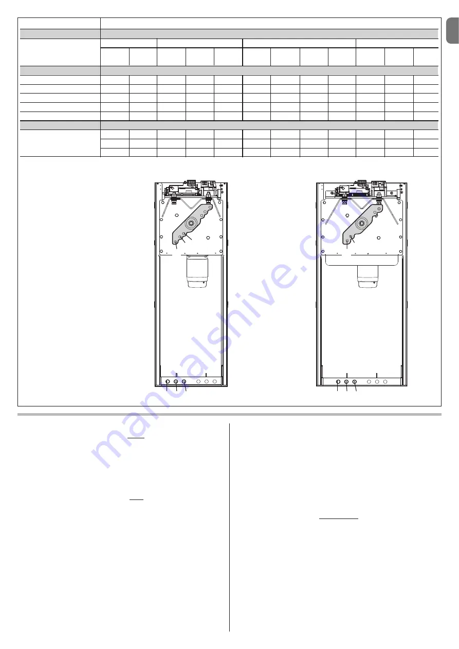
POSITION OF THE SPRING ANCHORING HOLE

0÷1 = B2 0÷1 = B3

0÷2 = A2 0÷2 = B1

0÷2 = A1 0÷2 = A3

2÷7 = B3 2÷4 = C1

3÷5 = A2 3÷5 = B2

3÷4 = A2 3÷6 = B1

5÷6 = C2

6÷7 = A3

5÷6 = A3

Example:

M5BAR with 4m pole + Rack 
(1piece) (value:1) + Pole lights
(value:1) = 

Sum of values: 2

Risult

= POSITION 

C1

A

M3BAR / M5BAR

M7BAR / LBAR

1

2

3

B

C

1

2

3

A

B

Summary of Contents for M3BAR

Page 1: ...ctions et avertissements pour l installation et l utilisation ES Instrucciones y advertencias para la instalaci n y el uso DE Installierungs und Gebrauchsanleitungen und Hinweise PL Instrukcje i ostrz...

Page 2: ......

Page 3: ...ngs On the power line to the system install a device for disconnection from the power mains with a gap between contacts that assures complete discon nection in the conditions of overvoltage category I...

Page 4: ...e S p a product catalogue The electromagnetic compatibility may not be guaranteed if the product is used in configurations or with other products that have not been foreseen the use of the product is...

Page 5: ...riers for residential and indus trial use they control the opening and closing of a road transit point with widths from 3 to 8 metres IMPORTANT All uses other than the intended use described and use i...

Page 6: ...aracteristics of electrical cables 3 3 1 Modifying the factory settings of the Closure manoeuvre If Closure to the right is required proceed as follows MBAR Version 01 Remove the cover fig 4 02 Loosen...

Page 7: ...ncy must be checked and ensure that the 4 anchoring points can resist a load of at least 1000 Kg For fixture use 12 MA screws 3 5 Pole installation 3 5 1 Pole support assembly 01 Insert the two plugs...

Page 8: ...fig 24 03 Insert the universal joint in the free ends of the two poles Take care in cor rectly directing the joint since the heads of the screws must be on the same part of the holes on the poles fig...

Page 9: ...output In the factory it is configured for operation with Pole Open Indicator 24 V 10 W BLUEBUS this terminal enables the connection of compatible devices all are connected in parallel with just two...

Page 10: ...rom the power mains and insert the receiver as shown in fig 42 Table 5 shows the actions performed by the control unit according to the out puts activated or the commands sent from the radio receiver...

Page 11: ...ing the optic axis joining the two photocells by means of a cylin der diameter 5 cm length 30 cm Fig C pass the cylinder first close to the TX photocell then close to the RX and lastly at the centre b...

Page 12: ...n Paragraph 4 5 EN 10 English The control unit has 3 keys OPEN STOP Set CLOSE Fig 49 that can be used both for controlling the unit during testing and for programming the available functions The progr...

Page 13: ...the type of voltage of the selected programming level 1LIGHT Output WARNINGS Do not set an excessively high value for the motor force as this may impair operation of the safety system or damage the p...

Page 14: ...he Set key for approx 3 seconds 02 Release the key when LED L1 starts flashing 03 Press the key or to move from the LED that is flashing to LED L4 LIGHT output input LED 04 Press and hold the Set key...

Page 15: ...ction opens FA1 and opens FA2 can be connected to the Bluebus input it is necessary to cut the A jumper at the rear of TX and RX cards When these photocells intervene the control unit commands an open...

Page 16: ...olution Off All OK CLOSE input not active On CLOSE input activation Normal if the device connected to the CLOSE input is active FC1 limit switch LED Cause Solution Off Limit switch activation If the p...

Page 17: ...n During normal operation indicates Stand BY active Flashes Programming of functions in progress If this flashes together with L3 this indicates that the device learning phase of the opening and closi...

Page 18: ...Loop activation time is the time t linked to the operating modes described in Table 16 Loop frequency display signals the fluctuation frequency of the loop selected in Hz 7 5 2 Installation WARNINGS...

Page 19: ...maximum temperature admitted for the isola tion of the cable otherwise a loss in isolation towards the earth may occur TABLE 15 Function Values Default Loop 1 sensitivity 10 100 90 Loop 2 sensitivity...

Page 20: ...it is possible to carry out the following connections its own flashing light Flash its own Pole Open Indicator S C A pole lights its own sensitive edge Stop its own command device P P which commands t...

Page 21: ...he event of illegal dis posal of this product The manoeuvre is performed but shortly afterwards the pole blocks or performs a brief inversion the selected force value may be too low to enable the move...

Page 22: ...output for signal indicator 24V max 10W Output for flashing light with optional accessories XBA7 LED flashing light or XBA8 LED traffic light traffic light on cover BLUEBUS output 1 output with maxim...

Page 23: ...cil of 21 December 1988 regarding the approximation of legislation regulations and administration of Member States concerning construction products according to the following harmonised standards EN 1...

Page 24: ...02 Radio spectrum art 3 2 EN 300 330 2 V1 5 1 2010 In accordance with directive 1999 5 CE annex V the product is classified as class 1 and marked DIRECTIVE 2004 108 EC OF THE EUROPEAN PARLIAMENT AND C...

Page 25: ...sh es and the manoeuvre is not started the number of flashes depends on the reason for which the manoeuvre does not start In this case the user must press and hold the command within three seconds Aft...

Page 26: ......

Page 27: ...he test procedure 10 Check protection against the risk of lifting on automations with vertical movement it must be ensured that there is no risk of lifting This test can be performed as follows hang a...

Page 28: ...lish Date Description of operation describe checks adjustments repairs modifications etc Signature of technician Signature of owner That all phases as envisaged in the maintenance schedule have been p...

Page 29: ...mm 464 5 mm 400 mm 1219 5 mm 900 mm M3BAR M5BAR M7BAR L Bar 298 5 mm 464 5 mm 500 mm 1219 5 mm 900 mm EN with joint IT con giunto FR avec raccord ES con uni n DE mit Gelenkverbindung PL ze z czk NL m...

Page 30: ...II 4 3 b a c d g h f e c a b...

Page 31: ...III 5 6 MBAR a c d b...

Page 32: ...IV 90 8 9 MBAR a b c a b 7 a b...

Page 33: ...V 180 10 11 LBAR c a a b...

Page 34: ...VI 13 14 12 LBAR c a b...

Page 35: ...VII 15 16 18 17...

Page 36: ...VIII 19 20 21 23 22...

Page 37: ...IX 24 26 25 28 1 cm 27 29...

Page 38: ...X 33 34 30 31 32 c a b c a b...

Page 39: ...XI 35 36 37 45 38 a b a b c...

Page 40: ...C NO NO C C MOTB MOFB OPEN CLOSE TX RX 24V 4W LIGHT FLASH SCA BLUEBUS STOP OPEN CLOSE P P LIGHT FLASH SCA BLUEBUS STOP OPEN CLOSE P P LOOP2 LOOP1 41 IN 1 IN 2 IN 3 LOOP 2 MASTER SLAVE LOOP 1 OUT 3 OUT...

Page 41: ...XIII 42 43 44 STOP 45 46 LIGHT 47...

Page 42: ...XIV 48 49 50 a b c...

Page 43: ...XV 51 52 a b...

Page 44: ...XVI 53 a b c d e f g...

Page 45: ...FLASH SCA MOTB OPEN CLOSE TX RX BLUEBUS STOP OPEN CLOSE P P 24V 4W BUS T4 M S LOOP2 LOOP1 LIGHT FLASH SCA BLUEBUS STOP OPEN CLOSE P P 24V 4W BUS T4 M S LOOP2 LOOP1 NC NC NO NO C C NC NC NO NO C C 54 M...

Page 46: ...XVIII F1 F1 F2 F2 55...

Page 47: ......

Page 48: ...ISTML BARR01 4865_07 10 2011 www niceforyou com Nice SpA Oderzo TV Italia info niceforyou com...

Reviews: