6
– English
English
INSTALLATION: COMPONENT ASSEMBLY AND CONNECTION
––– STEP 5 –––
IMPORTANT!
- The following assembly steps illustrate installation of the MAES-
TRO300M / MAESTRO300C gearmotor.
- For correct system operation it is necessary to supply mechanical
stops, on the ground or wall, positioned at the maximum Opening and
Closing points of the door.
Note
- These end stops are not included in
the kit and do not form part of the Nice Home product range.
WARNINGS
• Incorrect installation may cause serious physical injury to those
working on or using the system.
• Before starting automation assembly, carry out the preliminary
checks as described in STEP 3
.
5.1 - MAESTRO300C and MAESTRO300M GEARMOTOR
INSTALLATION
01.
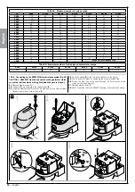
Measure distance “
B
” (
fig. 6
).
02.
Move the leaf to the desired maximum opening position, and check
whether the angle value found falls within the values listed in
Graph 4
.
03.
As shown in
fig. 4
, using value “
B
” and the opening angle, determine
value “
A
” (
fig. 7
).
Example: if “
B
” is 100mm and the angle required is
equal to 100°, the distance “
A
” is around 180 mm
.
04.
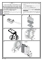
Affix the
mounting bracket of the gearmotor to the wall, in a hori-
zontal position, as shown in
fig. 8-1, 8-2, 8-3
: use suitable anchors,
screws and washers (not supplied);
05.
Affix the gearmotor to the previously mounted bracket, as shown in
fig. 8-4, 8-5
: us the M6x100 screw supplied;
06.
Now, affix the
curved arm to the arm using the pin and the ringed
stop (
fig. 8-6
)
; then affix the mounting bracket for the gate leaf to the
curved arm, using the pin and ringed stop (
fig. 8-6
);
07.
Manually release the gearmotor (
fig. 8-7
), see paragraph 11.3;
08.
Now, determine where to affix the bracket to the gate leaf, by extend
-
ing the gearmotor arms as far as possible (
fig. 8-8
): it is important to
position the bracket at the farthest point with respect to the position
of the gearmotor;
09.
Drill the leaf and affix the bracket, using suitable screws (not supplied)
(
fig. 8-9
);
10.
Before locking the gearmotor, adjust the opening mechanical stop
(paragraph 5.2).
5.2 - ADJUSTING THE OPENING MECHANICAL LIMIT
SWITCH
If, in your installation environment, there are no mechanical stops placed
on the ground, designed to stop the wings of the gate at the end of their
opening movement, it is necessary to adjust the mechanical stop on the
bottom side of each motor, in the following manner:
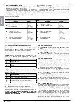
01.
Manually move the gate leaves to the fully open position;
02.
Rotate the plastic disc, located on the lower part of the gearmotor,
bringing the slot below the arm into the position shown in
fig. 9-1
;
03.
Insert the end stop into the first available position: try to insert it as
shown in
fig. 9-2
(opening direction);
04.
Turn the disc so that the end stop does not fall, by bringing the slot
into the position shown in
fig. 9-3
; for a more precise adjustment,
turn the adjustment screws (
fig. 9-4
);
05.
If there is no closing ground stop present in the system, it is necessary
to repeat the process from point 01 to adjust the closing end stop;
06.
Finally, screw the nut holding the disc down fully (
fig. 9-5
) to ensure
that it cannot accidentally rotate.
5.3 - MAESTRO300C and MAESTRO300M GEARMOTOR
CONNECTION
CAUTION! – All electrical connections must be made while discon-
nected from the grid and disconnected from the backup battery
(if any).
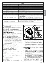
To make the electrical connections, remove the top cover of the gearmo-
tor as shown in
fig. 13-1
.
•
MAESTRO300C
: thread the cable through the appropriate duct locat-
ed on the back of the gearmotor, and make the electrical connections
as shown in
13-3
,
13-4
e
13-5
, richiudere il coperchio (
fig. 13-6
).
•
MAESTRO300C
: thread the cables through the appropriate duct
located on the back of the gearmotor, and make the electrical connec-
tions as shown in
fig. 12
, replace the cover.
Bearing in mind that:
01.
To facilitate connection operations, you can remove the terminals.
After having made the connections, insert the terminals back into
their dedicated seats.
02.
The MAESTRO300M cable is connected as shown in detail (
B
) in
fig.
12
.
03.
Remember that in order to avoid the risk of the two leaves colliding,
the MAESTRO300C command unit first commands the motor con-
nected to the M2 output to open, and then the motor connected to
M1, whilst during closing, the reverse happens. Then, make sure that
the (outer) terminal M1 is connected the motor that drives the leaf
resting on the mechanical stop, and terminal M2 to the top leaf.
If you are using only one motor (gate with only one leaf), connect it to
terminal M2, leaving terminal M1 free.
04.
The grey terminals (open) and red (stop) of the KS200KIT key selector
switch (optional accessory), are connected respectively to the grey
terminals (open) and red (stop) of the control unit. You do not need to
observe any polarity for the connection.
05.
If you are using an external antenna (optional accessory), you will need
to connect the control unit core and the screen of the shielded cable
as shown in detail (
A
) in
fig. 12
.
Summary of Contents for Maestro300
Page 2: ......
Page 10: ...8 Français Français 4 OK 3 NO 2 NO 1 180 2 2 180 1 9 10 11 1 3 4 5 2 ...
Page 28: ......
Page 36: ...8 English English 4 OK 3 NO 2 NO 1 180 2 2 180 1 9 10 11 1 3 4 5 2 ...
Page 54: ......
Page 62: ...8 Italiano Italiano 4 OK 3 NO 2 NO 1 180 2 2 180 1 9 10 11 1 3 4 5 2 ...
Page 80: ......
Page 88: ...8 Polski Polski 4 OK 3 NO 2 NO 1 180 2 2 180 1 9 10 11 1 3 4 5 2 ...
Page 106: ......
Page 119: ......


