12
– English
English
PROGRAMMING
––– STEP 7 –––
7.1 - POWER SUPPLY CONNECTION
WARNINGS!
– The PVC power cable is suitable for indoor installations. For
installation outdoors, you must protect the entire cable with a pro-
tective duct. Alternatively, you can replace the cable with one of
type H07RN-F.
– The final connection of the automation to the electrical mains or
substitution of the cable supplied must be performed exclusively
by a qualified and expert electrician, in compliance with local safe-
ty standards and the following instructions.
• For operational and programming tests of the automation
, use
the cable supplied, inserting the plug into an electrical socket. If the sock-
et is far from the automation, use a suitable extension lead.
• For the test and commissioning phase of the automation
you
must connect the control unit permanently to the mains power supply,
replacing the supplied cable with another of suitable length. To make the
connection between the cable and the gearmotor control unit, proceed as
described below:
WARNING:
Provide a device inside the electricity supply line that ensures complete
disconnection of the automation mechanism from the grid. The dis-
connection device must have contacts with an opening distance large
enough to permit complete disconnection under the conditions sanc-
tioned by overvoltage category III, in accordance with installation regula-
tions.
The device ensures quick, safe disconnection from the power sup-
ply if needed, and must therefore be positioned in view of the automation
mechanism. If, on the other hand, it is located in a position which is not
visible, there must be a system for preventing accidental or unauthorized
reconnection with the power grid to prevent this risk. The disconnection
device is not supplied with the product.
01.
Make sure that the gearmotor plug is not plugged into the wall socket.
02.
Disconnect the power supply terminal electrical cable from the gear-
motor.
03.
Loosen the collar found under the terminal and remove the electric
cable.
Replace it with a permanent power supply cable.
04.
Connect the electric cable to the gearmotor power supply terminal.
05.
Tighten the collar to secure the electric cable.
7.2 - PRELIMINARY CHECKS
As soon as the control unit is electrically powered, you are advised to
carry out some simple tests:
01.
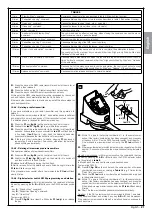
Check that the
ECSbus led
[A]
(
fig. 16
) is flashing steadily, at a
speed of around one flash per second.
02.
Check that the
SAFE led
[B]
(
fig. 16
) on the photocells is flashing
(both on TX and RX); the type of flash is not important as this depends
on other factors; it is simply important that it is not either permanently
lit or unlit.
03.
If the above conditions are not satisfied, it is advisable to switch off
the power supply to the control unit and check the electrical connec-
tions more carefully. For other useful information see also chapters
10.5 “Troubleshooting” and 10.6 “Diagnostics and signals”.
7.3 - CONNECTED DEVICES RECOGNITION
Once the initial checks are complete, you need to allow the control unit
to recognise the devices connected to it on the “ECSbus” and “STOP”
terminals.
01.
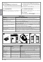
On the control unit, press and hold down
P2
[A]
(
fig. 17
) for at least
3 seconds, then release it.
02.
Wait a few seconds until the control unit has completed the device
recognition procedure.
03.
On recognition completion the
STOP led
[B]
(
fig. 17
) must remain
lit, whilst the
P2 led
[C]
(
fig. 17
) must go out. If the
P2 led
flashes, it
means that an error has occurred; see section 10.5 “Troubleshooting”.
The phase of self-learning the devices connected can be repeated at any
time also after installation (such as in the case that a photocell is added);
it is sufficient to repeat it from point 01.
7.4 - GATE LEAF OPEN AND CLOSURE ANGLES RECOG-
NITION
After self-learning the devices, the control unit must recognise the leaf
opening and closing angles. In this phase the opening angle of the leaves
from the mechanical end closing stop up to the mechanical opening stop
is detected. The presence of fixed and sufficiently robust mechanical
stops is essential.
01.
Carry out motors release using the appropriate keys (see paragraph
11.3 - Usage guide) and move the leaves to mid-course, in such a
way that they are free to move in the opening and closing directions;
then release the motors.
02.
On the control unit press and release
P3
[B]
(
fig. 17
); wait for the
control unit to perform the recognition: closure of motor M1 up to the
mechanical stop, closure of motor M2 up to the mechanical stop,
opening of the motor M2 and the motor M1 up to the mechanical
opening stop; full closure of M1 and M2.
- If the first manoeuvre of one or both wings is not a closure, press
P3
to stop the recognition phase and then invert the polarity of the
opening motor(s) by swapping over the two brown and blue wires on
the terminal.
- If the first motor to carry out a closing move is not M1, press
P3
to
stop the recognition phase and then swap the motors connections
on the terminals.
- If during the recognition phase a device actuates (photocells, key
selector switch, P3 pressed, etc.) the recognition phase will be
stopped immediately. It will then be necessary to repeat it in full.
03.
If the
P3 led
[A]
(
fig. 17
) flashes at the conclusion of the recognition
process, it means that an error has occurred; see section 10.5 “Trou-
bleshooting”.
The recognition stage of the opening angles can be repeated again at any
time, even after the installation (for example, if one of the opening stops is
moved); it is sufficient to repeat the procedure starting from step 1.
7.5 - RADIO TRANSMITTERS CHECK
To check the transmitters, you just need to press on one of its 4 keys,
check that the led flashes and that the automation carries out the com-
mand sent.
The command associated to each key depends on the way in which they
were stored (see paragraph 10.4 “Memorisation of radio transmitters”).
7.6 - ADJUSTMENTS
7.6.1 - Leaf speed selection
Leaf opening and closing can be done in two speeds: “slow” or “fast”.
To move between one speed and the other, quickly press
P2
(
fig. 17
); the
corresponding
P2 led
(
fig. 17
) lights up or goes out; when the led is off
the speed is “slow”, when the led is lit the speed is “fast”.
7.6.2 - Selecting the operating cycle type
The closing and opening of the gate can be performed according to two
different operating cycles:
• single cycle (semiautomatic): with one command the gate opens, and
will remain open until the next command causing it to close.
• Complete cycle (automatic closure): with one command, the gate opens
and recloses automatically after a short space of time (for the duration
see paragraph 10.1 “Parameter adjustment using radio transmitter”).
To move between one operating cycle and the other, quickly press
P3
(
fig. 17
); the corresponding led (
fig. 17
) lights up or goes out; when the
led is off the cycle is “single”, when the led is lit the cycle is “complete”.
Summary of Contents for Maestro300
Page 2: ......
Page 10: ...8 Français Français 4 OK 3 NO 2 NO 1 180 2 2 180 1 9 10 11 1 3 4 5 2 ...
Page 28: ......
Page 36: ...8 English English 4 OK 3 NO 2 NO 1 180 2 2 180 1 9 10 11 1 3 4 5 2 ...
Page 54: ......
Page 62: ...8 Italiano Italiano 4 OK 3 NO 2 NO 1 180 2 2 180 1 9 10 11 1 3 4 5 2 ...
Page 80: ......
Page 88: ...8 Polski Polski 4 OK 3 NO 2 NO 1 180 2 2 180 1 9 10 11 1 3 4 5 2 ...
Page 106: ......
Page 119: ......


