English
20
Photocells and other devices using this system can be connected to
ECSBus, such as safety devices, control buttons, indicator lights etc. For
information on ECSBus devices, refer to the Mhouse catalogue or visit the
website www.niceforyou.com
A special learning phase enables the control unit to recognise all con
-
nected devices individually, and enables precise diagnostics procedures.
For this reason, each time a device connected to ECSBus is added or
removed, the learning phase must be performed on the control unit; see
paragraph 10.3.3 “Learning other devices”.
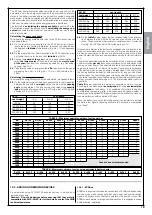
10.3.2 - STOP Input
STOP is the input that causes immediate shutdown of the movement (fol
-
lowed by a brief inversion of the manoeuvre). This input can be connected
to devices with contact types Normally Open (NO, as in the case of the
KS100 selector switch), Normally Closed (NC) or devices with a constant
resistance of 8.2 K
Ω
, such as sensitive edges.
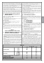
When set accordingly, more than one device can be connected to the
STOP input, also different from one another; see
Table 8
.
Note 1.
The NO and NC combination can be obtained by placing the
two contacts in parallel, and placing an 8.2k
Ω
resistance in series with
the NC contact (it is, therefore, possible to combine 3 devices:
NA, NC
and 8,2k
Ω
).
Note 2.
Any number of NO devices can be connected to each other in
parallel.
Note 3.
Any number of NC devices can be connected to each other in
series.
Note 4.
Only two devices with an 8.2 k
Ω
constant resistance output can
be connected in parallel; multiple devices must be connected “in cas-
cade” with a single 8.2 k
Ω
termination resistance.
Caution! – If the STOP input is used to connect devices with safety
functions, only the devices with 8.2 k
Ω
constant resistance output
will guarantee the fail-safe category .
As with the ECSBus, the control unit recognises the type of device con
-
nected to the STOP input during the learning phase; subsequently the
control unit gives a STOP command when it detects a variation with
respect to the learned state.
10.3.3 - Recognition of other devices
The learning operation of the devices connected to the ECSBus and
STOP input is usually carried out during the installation phase; if devices
are added or removed the learning operation can be carried out again as
follows:
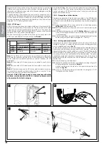
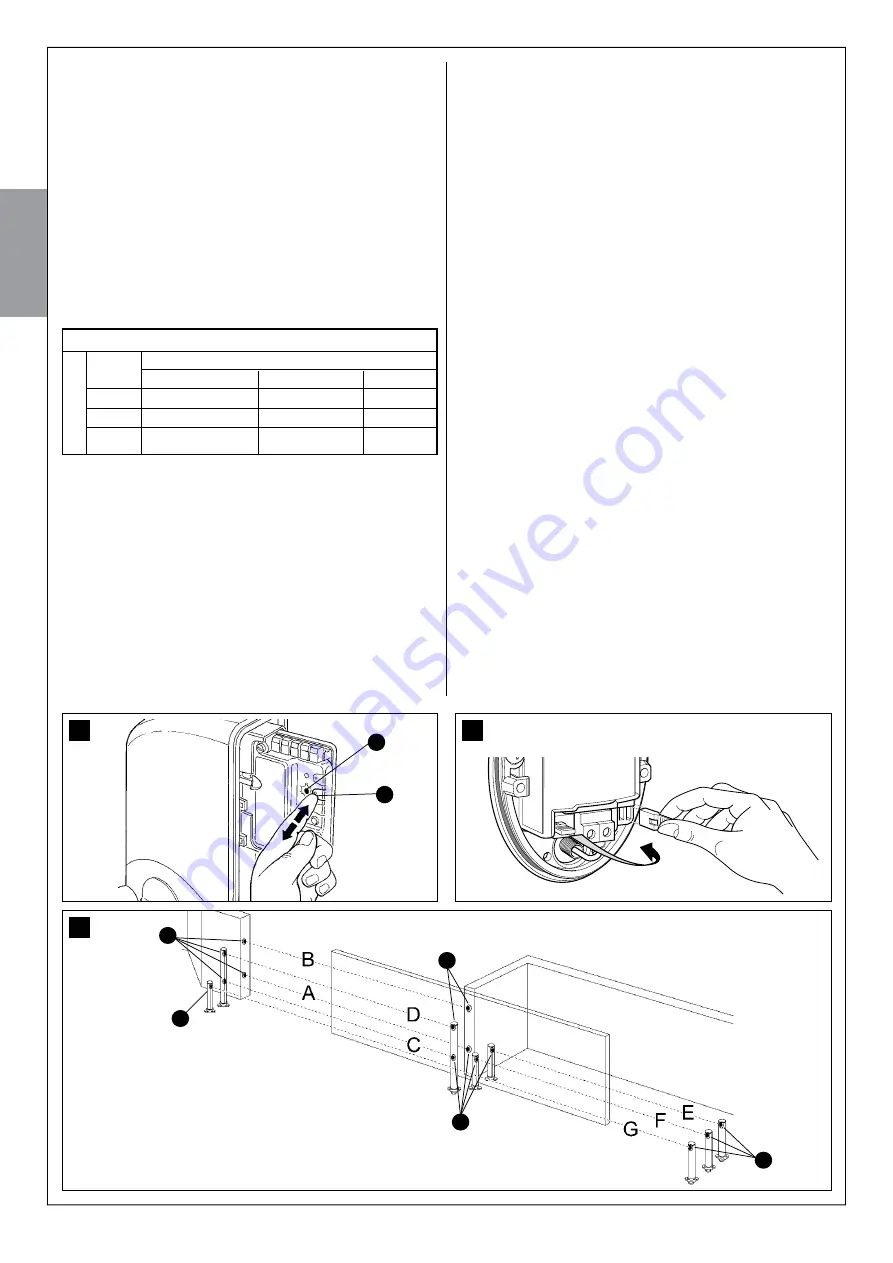
01.
Press and hold key P2 on the control unit for at least three seconds
[B] (fig. 40)
, then release the key.
02.
Wait a few seconds to allow the control unit to finish learning the
devices.
03.
At the end of the learning the LED P2
[A] (fig. 40)
should switch off.
If the LED P2 flashes it means there is an error; see paragraph 10.5
“Troubleshooting”.
04.
After having added or removed a device the automation test must be
carried out again as specified in paragraph 8.1 “Testing”.
10.3.4 - Adding optional photocells
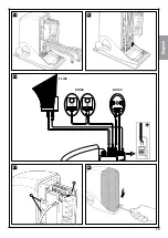
Additional photocells to those supplied with the SL1S-SL10S can be
installed at any time. In systems for the automation of sliding gates they
must be installed as shown in
fig. 41
.
In order for the control unit to correctly recognise the photocells they must
be assigned with addresses using special electric jumpers. The address
assignment operation must be carried out on both TX and RX (placing the
electric jumpers in the same way) and it is important to check that there
are not any other pairs of photocells with the same address. The photo
-
cell address assignment operation is necessary for them to be correctly
recognised among the other devices of the ECSBus and to assign them
their function.
01.
Open the housing of the photocell.
02.
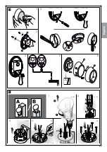
Identify the position in which they are installed according to Figure 70
and place the jumper according to
Table 9
.
Unused jumpers must be placed in the special compartment for
future use (
fig. 42
).
03.
Carry out the learning phase as described in paragraph 10.3.3
“Re cognition of other devices”.
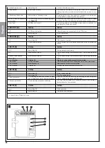
41
Tx
Tx
Rx
Rx
Tx
1
st device type:
NA
NC
8,2 K
Ω
NA
In parallel (
note 2
)
(
note 1
)
In parallel
NC
(
note 1
)
In series (
nota 3
)
In series
8,2K
Ω
In parallel
In series
(
nota 4
)
TABLE 8
2
nd
device
type:
40
B
A
42
Summary of Contents for MhouseKit SL10S
Page 2: ......
Page 7: ...Fran ais 7 2 300 163 295 84 4 E D A F D B D C D 3 i d e g h a d b b c f l 1 A C D E F B G...
Page 9: ...Fran ais 9 5 7 8 9 10 0 50 moteur fix gauche moteur fix droite 6 36 50 0 50 50...
Page 10: ...Fran ais 10 11 12 14 13 170 170 1 200 200...
Page 11: ...Fran ais 60 11 16 18 19 17 10 0 50 0 50 10 moteur fix gauche moteur fix droite 15 A...
Page 13: ...Fran ais 21 A B 6 mm x4 A B A B A B B B B 1 2 3 4 1 2 3 4 20 B C A 13 5 D E F 6...
Page 14: ...Fran ais 14 22 23 21 A B A B A B A B A B A B 5 6 7 8 9 11 12 10 A B A B 6 mm x4 A A A A 4...
Page 15: ...Fran ais 15 24 25 TX RX 26 FL100 PH100 KS100 A 28 27 A B...
Page 17: ...Fran ais 17 31 B A C 34 32 A A B 35 A B 30 A B 33 T1 T2 T3 T4...
Page 34: ......
Page 39: ...English 5 2 300 163 295 84 4 E D A F D B D C D 3 i d e g h a d b b c f l 1 A C D E F B G...
Page 41: ...English 7 5 7 8 9 10 0 50 motor fixed on left motor fixed on right 6 36 50 0 50 50...
Page 42: ...English 8 11 12 14 13 170 170 1 200 200...
Page 43: ...English 9 18 19 60 17 10 0 50 0 50 10 motor fixed on left motor fixed on right 15 A 16...
Page 45: ...English 11 21 A B 6 mm x4 A B A B A B B B B 1 2 3 4 1 2 3 4 5 20 6 B C A D E F...
Page 46: ...English 12 22 23 21 A B A B A B A B A B A B 5 6 7 8 9 11 12 10 A B A B 6 mm x4 A A A A 4...
Page 47: ...English 13 24 25 TX RX 26 FL100 PH100 KS100 A 28 27 A B...
Page 49: ...English 15 31 B A C 34 32 A A B 35 A B 30 A B 33 T1 T2 T3 T4...
Page 66: ......
Page 71: ...Italiano 5 2 300 163 295 84 4 E D A F D B D C D 3 i d e g h a d b b c f l 1 A C D E F B G...
Page 73: ...Italiano 7 5 7 8 9 10 0 50 motore fissato a sinistra motore fissato a destra 6 36 50 0 50 50...
Page 74: ...Italiano 8 11 12 14 13 170 170 1 200 200...
Page 77: ...Italiano 11 21 A B 6 mm x4 A B A B A B B B B 1 2 3 4 1 2 3 4 20 B C A 5 D E F 6...
Page 78: ...Italiano 12 22 23 21 A B A B A B A B A B A B 5 6 7 8 9 11 12 10 A B A B 6 mm x4 A A A A 4...
Page 79: ...Italiano 13 24 25 TX RX 26 FL100 PH100 KS100 A 28 27 A B...
Page 81: ...Italiano 15 31 B A C 34 32 A A B 35 A B 30 A B 33 T1 T2 T3 T4...
Page 98: ......
Page 103: ...5 2 300 163 295 84 4 E D A F D B D C D 3 i d e g h a d b b c f l 1 A C D E F B G...
Page 106: ...8 11 12 14 13 170 170 1 200 200 Polski...
Page 109: ...11 21 A B 6 mm x4 A B A B A B B B B 1 2 3 4 1 2 3 4 20 B C A 5 D E F 6 Polski...
Page 110: ...12 22 23 21 A B A B A B A B A B A B 5 6 7 8 9 11 12 10 A B A B 6 mm x4 A A A A 4 Polski...
Page 111: ...13 24 25 TX RX 26 FL100 PH100 KS100 A 28 27 A B Polski...
Page 113: ...15 31 B A C 34 32 A A B 35 A B 30 A B 33 T1 T2 T3 T4 Polski...
Page 130: ......
Page 131: ......


