GB
9
After making connections perform a general test, i.e.:
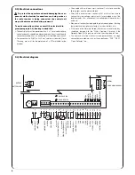
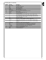
• Power the control unit and immediately check whether terminals 1-2 are mains powered and terminals 15-16 (services output) are
powered at approx. 28Vdc. If this is not the case, unplug the unit immediately and carefully check the connections and the voltage input.
• After about 2 seconds from switching on, the “OK” Led should show the control unit is working correctly by flashing regularly at 1 second
intervals.
• Check that the led’s relative to the NC inputs (“Stop”, “Photo” and “Photo2”) are on (safety devices active) and that the led’s relative to the
NO inputs are off (no command present); if this is not the case, check the connections of the various devices and make sure they are in
good working order.
• Check that all the safety devices of the unit are in proper working order (emergency stop, photocells, pneumatic edges, etc.); each time
they cut in, the relative “Stop”, “Photo” or “Photo2” led’s should turn off.
• Check the motor turns in the right direction, i.e.:
♦
release the motor and check that the release led on the board is on
♦
move the door manually so that it is free to move during the opening and closing manoeuvres;
♦
block the motor again and check that the release led is off
♦
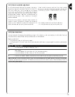
press the “Close” button (ref. K of Fig. 1) and check that the door moves in the close direction
♦
if the opening manoeuvre is performed, press again on the close button to stop the door from moving, unplug the machine and invert
the two motor wires
♦
regardless of the direction of movement, press the “Close” button again to stop the manoeuvre immediately
Once the connections have been successfully tested, the search for mechanical stops phase can begin.
This operation is important because the A924 control unit must measure the space covered by the motor, in terms of the number of encoder
impulses, to move the door from the maximum close position (position 0) to the maximum open position (position 1).
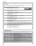
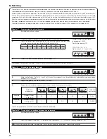
Position 0 and position 1 act as reference points for all the other positions indicated on the graph in
Fig 4
.
POSITION 0:
is the point at which the sectional door is in the closed position, corresponding
to the mechanical stop (generally the floor).
POSITION 1:
is the point at which the sectional door is in the maximum open position,
corresponding to the mechanical opening stops (point M).
POSITION A:
is the point at which the door is required to stop during the opening manoeuvre
(this does not necessarily coincide with the mechanical stops in the opening cycle).
POSITION B:
is the position in which the door is required to stop during the partial opening
manoeuvre.
POSITION RA:
is the position in which the door is required to begin slowing down during the
normal opening manoeuvre.
POSITION RC:
is the position in which the door is required to begin slowing down during the
closing manoeuvre.
The mechanical stops can be searched by means of an initial search, an automatic search or manual programming. After an “initial search”
or “automatic search”, one or more automatically detected positions can be modified by means of manual programming, if required, except
positions 0 and 1 which act as references for all the others.
3) Programming
2.7) Checking connections
The next operations involve work being done on live
circuits, some parts have mains voltage running through
them and are therefore extremely dangerous!
Pay the greatest of attention to what you are doing and
never work alone!
!
1
M
A
RA
B
RC
0
Summary of Contents for Mindy A924
Page 2: ...mindy...
Page 3: ...A924...
Page 19: ...19 Nice reserves the right to modify the products whenever it sees fit...


