EN
English –
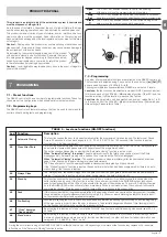
9
L7
L1
L2
L3
L4
L5
L6
L7
L8
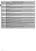
Automatic (depending on the severity of the manoeuvre)
1000
2000
4000
7000
10000
15000
20000
Adjusts the number of manoeuvres
after which it signals the maintenan-
ce request of the automation (see
paragraph “Maintenance warning”).
Mainte-
nance
warning
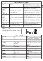
L8
L1
L2
L3
L4
L5
L6
L7
L8
1
a
manoeuvre result
2
a
manoeuvre result
3
a
manoeuvre result
4
a
manoeuvre result
5
a
manoeuvre result
6
a
manoeuvre result
7
a
manoeuvre result
8
a
manoeuvre result
List of
malfun-
ctions
L6
L1
L2
L3
L4
L5
L6
L7
L8
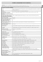
0,5 mt
1 mt
1,5 mt
2 mt
2,5 mt
3 mt
3,4 mt
4 mt
Adjusts the measurement of the par-
tial opening. Partial opening can be
controlled with the 2nd radio com-
mand or with “CLOSE”, if the “Clo-
se” function is present, this becomes
“Open partially”.
Open
Partially
Note: “
” represents the factory setting
All the parameters can be adjusted as required without any contraindication; only the adjustment of the “motor force” could require special care:
• Do not use high force values to compensate for points of abnormal friction on the leaf. Excessive force can compromise the operation of the safety system or damage the leaf.
• If the “motor force” control is used to assist the impact force reduction system, measure the force again after each adjustment in compliance with EN standard 12445.
• Wear and weather conditions may affect the movement of the gate, therefore periodic force re-adjustments may be necessary.
The type of defect that has occurred
in the last 8 manoeuvres can be
established (see paragraph “9.2 Mal-
functions archive”).
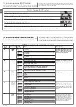
TABLE 8
-
Changing the adjustable parameters
01.
Press the key “
Set
” and hold it down (approx. 3 s);
02.
Release the “
Set
” key when
L1
LED starts flashing;
03.
Press the key “
s
” or “
t
” to move the flashing LED onto the input LED representing the parameter which is to be changed;
04.
Press the key “
Set
” and hold it down during step 5 and 6;
05.
Wait approx. 3 seconds, after which the LED representing the current level of the parameter which is to be modified will light up;
06.
Press key “
s
” or “
t
” to move the LED representing the parameter value;
07.
Release the key “
Set
”;
08.
Wait 10 seconds before leaving the programme to allow the maximum time to lapse.
Note
– Points 3 to 7 can be repeated during the same programming phase in order to set other parameters
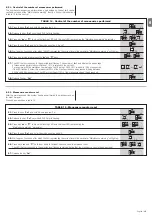
Programming examples: level one and level two
Level one:
The sequence to follow in order to change the factory settings of the functions for activating “
Automatic Closing
” (L1) and “
Always close
”
(L3) have been included as examples:
01.
Press the key
Set
and hold it down (approx. 3 s);
02.
Release the
Set
key when
L1
LED starts flashing;
03.
Press the
Set
key once to change the state of the function associated with
L1
(Automatic Closing).
LED
L1
will now flash with long flashes;
04.
Press the
t
key twice to move the flashing LED to LED
L3
;
05.
Press the
Set
key once to change the state of the function associated with
L3
(Always Close).
LED
L3
will now flash with long flashes;
06.
Wait 10 seconds before leaving the programme to allow the maximum time to lapse.
Once these operations have been completed, LEDs
L1
and
L3
must remain on to indicate that the “Automatic Closing” and the “Always Close” functions
are active.
Stop/Se
t
Stop/Se
t
Stop/Se
t
Stop/Se
t
L1
Ope
n
Clos
e
o
Ope
n
Clos
e
o
10 s
3 s
Stop/Se
t
L1
Stop/Se
t
3 s
L1
Stop/Se
t
L3
Stop/Se
t
10 s
L3
Clos
e
2x
Summary of Contents for Naked Sliding NKSL400
Page 2: ......
Page 43: ...I 405 mm 131 mm 135 mm 1 3 4 5 b d c c h l b f m g i n e a E C F D C F A B 2...
Page 44: ...II b a b a c 5 mm 6 7 10 11 8 9...
Page 46: ...IV 14 15...
Page 48: ...VI 19 20 a b c d e...
Page 49: ...VII 21 22...
Page 50: ......
Page 51: ......


