EN
English –
13
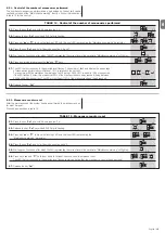
TABLE 14
-
Control of the number of manoeuvres performed
01.
Press the key “
Set
” and hold it down (approx. 3 s);
02.
Release the key “
Set
” key when
L1
LED starts flashing;
03.
Press key “
s
” or “
t
” to move the flashing LED onto the input LED representing the “Maintenance warning” parameter;
04.
Press the key “
Set
”, and hold it down during step 5, 6 and 7;
05.
Wait approx. 3 seconds, after which the LED representing the current level of the parameter “Maintenance warning” will light up;
06.
Press and immediately release the “
s
” and “
t
” keys;
07.
The LED that corresponds to the selected level flashes. The number of flashes indicates the percentage
of manoeuvres performed(in multiples of 10%) in relation to the set limit.
For example: with the maintenance warning set on L6 being 10000, 10% is equal to 1000 manoeuvres;
.... n=?
if the LED flashes 4 times, this means that 40% of the manoeuvres have been reached (being between
4000 and 4999 manoeuvres). The LED will not flash if 10% of the manoeuvres hasn’t been reached.
08.
Release the key “
Set
”.
TABLE 15
-
Manoeuvre counter reset
01.
Press the key “
Set
” and hold it down (approx. 3 s);
02.
Release the key “
Set
” key when
L1
LED starts flashing;
03.
Press key “
s
” or “
t
” to move the flashing LED onto the input LED representing the
“Maintenance warning” parameter;
04.
Press the key “
Set
”, and hold it down during step 5 and 6;
05.
Wait approx. 3 seconds, after which the LED representing the current level of the parameter “Maintenance warning” will light up;
06.
Press keys “
s
” and “
t
”, hold them down for at least 5 seconds and then release them.
The LED that corresponds to the selected level flashes rapidly indicating that the; manoeuvre counter has been reset
07.
Release the key “
Set
”.
8.2
.5
- Manoeuvre counter reset
After the maintenance of the system has been performed the manoeuvre coun-
ter must be reset.
Proceed as described in table 15.
8.2
.4
- Control of the number of manoeuvres performed
The number of manoeuvres performed as a percentage on the set limit can be
verified by means of the “Maintenance warning” function. Follow the indications
in table 14 for this control.
Stop/Se
t
L1
Stop/Se
t
Stop/Se
t
Stop/Se
t
Ope
n
Clos
e
Ope
n
Clos
e
o
e
3s
3s
L7
Stop/Se
t
L1
Ope
n
Clos
e
o
Stop/Se
t
Stop/Se
t
Stop/Se
t
Ope
n
Clos
e
L7
e
3s
3s
Summary of Contents for Naked Sliding NKSL400
Page 2: ......
Page 43: ...I 405 mm 131 mm 135 mm 1 3 4 5 b d c c h l b f m g i n e a E C F D C F A B 2...
Page 44: ...II b a b a c 5 mm 6 7 10 11 8 9...
Page 46: ...IV 14 15...
Page 48: ...VI 19 20 a b c d e...
Page 49: ...VII 21 22...
Page 50: ......
Page 51: ......


