12
– ENGLISH
FINAL CHECKS AND START-UP
5
5
FINAL CHECKS AND START-UP
It is advisable to position the leaf approximately halfway along
its path before starting the automation check and start-up phas-
es, so that the leaf is free to open and close.
5.1 POWER SUPPLY CONNECTION
a
The power supply connections must only be made
by qualified and experienced personnel possessing
the necessary requirements and in full conformity
to the laws, regulations and standards in force.
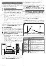
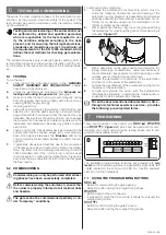
As soon as the product is powered, a few simple checks should
be carried out:
1.
check that the “
BlueBUS
” LED flashes regularly with one
flash per second
2.
check that the LEDs on the photocells (both the TX and
RX) also flash; the type of flashing is irrelevant, since it
depends on other factors
3.
check that the warning light connected to the FLASH out-
put is off.
If the above conditions are not satisfied, immediately switch
off the power supply to the control unit and carefully check the
electrical connections.
Further useful information on searching and diagnosing faults is
included in the “
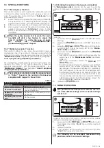
5.2 DEVICE LEARNING
Once the power supply has been connected, the control unit
must recognise the devices connected to the “
BlueBUS
” and
“
STOP
” inputs. Prior to this phase, LEDs “
L1
” and “
L2
” will flash
to signal that the device learning procedure must be performed.
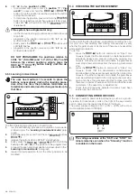
m
The learning phase must be carried out even if no
device is connected to the control unit.
To do this:
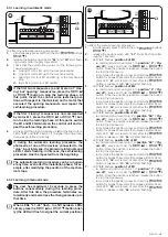
1.
simultaneously press and hold the
f
and
g
buttons
2.
release the buttons when LEDs
“L1”
and
“L2”
start flash-
ing quickly (after roughly 3 seconds)
3.
wait a few seconds until the control unit has completed the
device learning phase
4.
once this phase terminates, the
“Stop”
LED must be lit
and LEDs
“L1”
and
“L2”
must switch off (LEDs “
L3
” and
“
L4
” could start flashing).
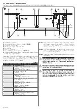
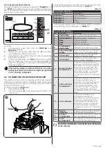
FLASH
EL
ST
OP
SBS
OPEN
BLUEBUS
L1
L2
26
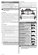
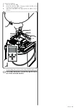
The learning process of connected devices can be repeated
at any time, even after the installation (for example, whenever a
device must be added); to complete the new learning process,
5.3 LEARNING OF THE MECHANICAL STOP
POSITIONS
Once the connected devices have been learned, the mechan-
ical stop positions must be learned (maximum opening and
maximum closing). This procedure can be carried out in three
different ways:
automatic
,
manual
and
mixed
.
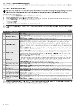
In the
automatic
mode, the control unit learns the mechanical
stops and calculates the most appropriate offsets for the
“SA”
and
“SC”
doors (“
Figure
“).
a
Before starting the self-learning procedure in auto-
matic mode, verify that the motor force is suited to
the type of motor being used (see paragraph “Level
2 programming (adjustable parameters) - Function
L5“).
In the
manual
mode, the positions (“
Figure
”) are pro-
grammed one by one, by shifting the leaves to the desired
points. The position to be programmed is signalled when one of
the six LEDs
“L1...L6”
In the
mixed
mode, it is possible to perform the automatic proce-
dure and then, with the manual procedure, modify one or more
positions with the exception of the
“0”
and
“1”
positions (“
Fig-
ure
”) which correspond to the mechanical stop positions.
1
1
SC
M1
M2
SA
0
0
27
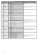
Table 4
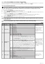
PROGRAMMING POSITIONS
Position
LED Description
Position 0
(motor 1)
L1
maximum closing position: when the leaf
relative to motor 1 strikes the closing
mechanical stop
Position 0
(motor 2)
L2
maximum closing position: when the leaf
relative to motor 2 strikes the closing
mechanical stop
Position SA
(motor 2)
L3
Position after which the leaf relative to
motor 1 starts opening
Position SC
(motor 1)
L4
Position after which the leaf relative to
motor 2 starts closing
Position 1
(motor 1)
L5
Maximum opening position: when the leaf
relative to motor 1 strikes the opening
mechanical stop
Position 1
(motor 2)
L6
Maximum opening position: when the leaf
relative to motor 2 strikes the opening
mechanical stop


