


Polski –
11
PL
• Wykaz historii anomalii
Ta funkcja umożliwia wyświetlanie ewentualnych anomalii, które wystąpiły pod-
czas wykonywania ostatnich 8 manewrów, na przykład przerwa manewru spo-
wodowana przez zadziałanie fotokomórki lub listwy optycznej. Aby sprawdzić
wykaz anomalii postępuj zgodnie z opisem z
Tabeli 12
.
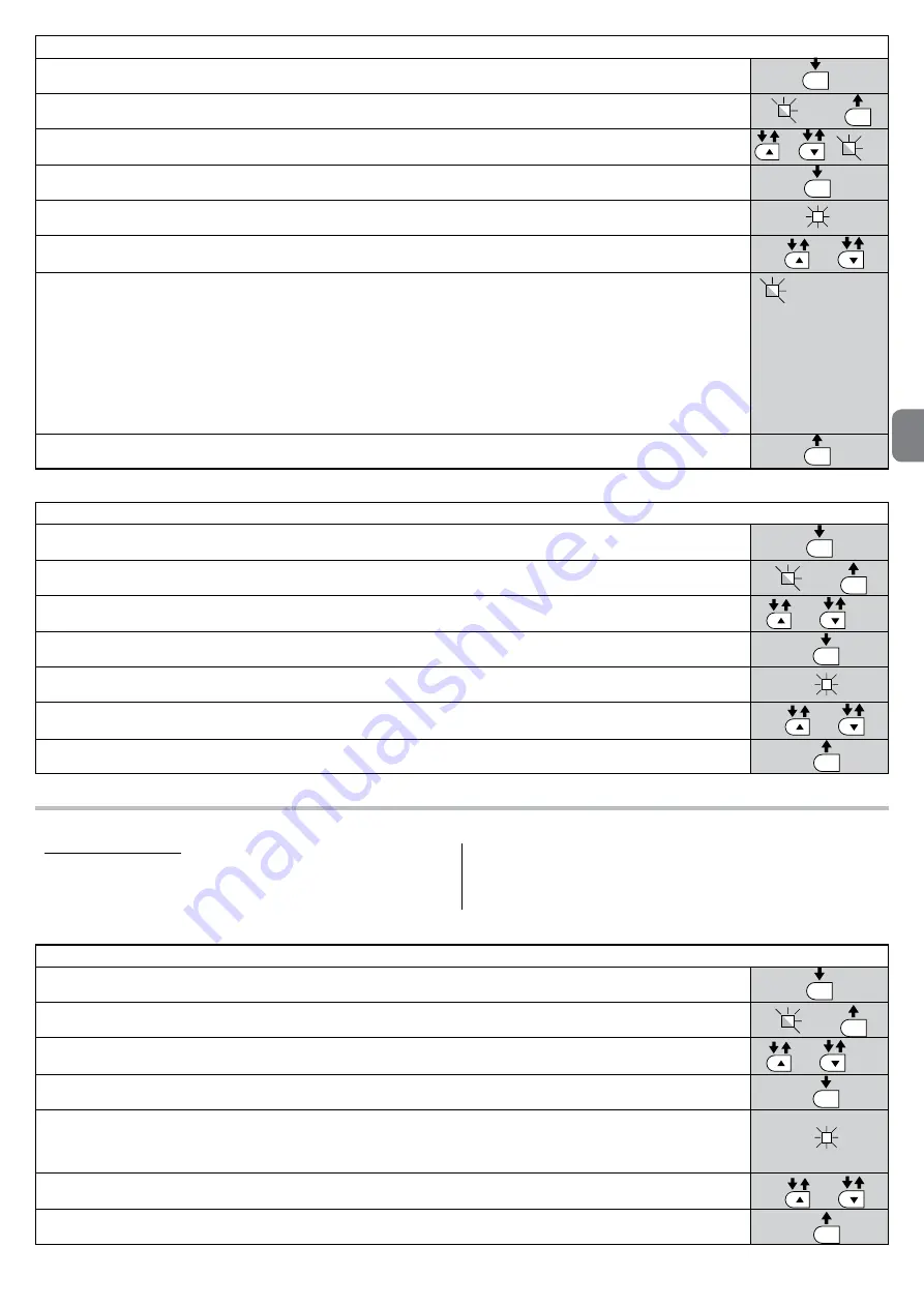
TABELA 10
01.
Wciśnij i przytrzymaj przycisk “
Set
” przez około 3 sekundy;
02.
Zwolnij przycisk, kiedy dioda “
L1
” zacznie migać;
03.
Wciśnij przycisk “
s
” lub “
t
, aby przesunąć się z migającej diody na diodę L7;
04.
Wciśnij i przytrzymaj przycisk “
Set
”, aż do zakończenia punktu 07;
05.
Odczekaj około 3 sekundy, aż do zaświecenia się diody, która reprezentuje aktualny poziom parametru „Zawiadomienie o kon-
serwacji;
06.
Wciśnij i natychmiast zwolnij przyciski “
s
” i “
t
”;
07.
Teraz dioda odpowiadająca wybranemu poziomowi wykona kilka błysków. Ilość błysków określa procentową ilość
wykonanych manewrów (wielokrotność 10%) w stosunku do ustawionego limitu.
Przykład: ustawiając zawiadomienie o konserwacji na L7 (10000), 10% odpowiada 1000 manewrów; jeżeli dioda
sygnalizacyjna wykona 4 błyski oznacza to, że zostało uzyskanych 40% manewrów (od 4000 do 4999 manewrów).
Jeżeli nie zostało osiągniętych co najmniej 10% manewrów nie nastąpi żadne miganie;
08.
Zwolnij przycisk “
Set
” .
SET
x 1 = 10-19%
x 2 = 20-29%
x 3 = 30-39%
x 4 = 40-49%
x 5 = 50-59%
x 6 = 60-69%
x 7 = 70-79%
x 8 = 80-89%
x 9 = 90-99%
x 10 = > 100%
L1
3 s
3 s
SET
SET
SET
/
/
L7
TABELA 11
01.
Wciśnij i przytrzymaj przycisk “
Set
” przez około 3 sekundy;
02.
Zwolnij przycisk, kiedy dioda “
L1
” zacznie migać;
03.
Wciśnij przycisk “
s
” lub “
t
”, aby przesunąć się z migającej diody na diodę L7 (dioda wejścia “Zawiadomienie o konserwacji”);
04.
Wciśnij i przytrzymaj przycisk “
Set
”, aż do zakończenia punktu 07;
05.
Odczekaj około 3 sekundy, aż do zaświecenia się diody, która reprezentuje aktualny poziom parametru „Zawiadomienie
o konserwacji;
06.
Wciśnij i przytrzymaj przyciski “
s
” i “
t
” przez co najmniej 5 sekund; następnie zwolnij oba przyciski. W tej fazie dioda
odpowiedniego poziomu wykona serię szybkich błysków, aby zasygnalizować wyzerowanie manewrów
07.
Zwolnij przycisk “
Set
” .
/
/
L7
L1
3 s
3 s
SET
SET
SET
SET
TABELA 12
01.
PWciśnij i przytrzymaj przycisk “
Set
” przez około 3 sekundy;
02.
Zwolnij przycisk, kiedy dioda “
L1
” zacznie migać;
03.
Wciśnij przycisk “
s
” lub “
t
”, aby przesunąć się z migającej diody na diodę L8 (dioda wejścia “Wykaz anomalii”);
04.
Wciśnij i przytrzymaj przycisk “
Set
”, aż do zakończenia punktu 06;
05.
Odczekaj około 3 sekundy, dopóki nie zaświecą się diody odpowiadające manewrom, które wykazały anomalie. Dioda L1
wskazuje wynik ostatniego wykonanego manewru, dioda L8 wskazuje wynik ósmego manewru. Jeżeli dioda świeci
się, oznacza to, że podczas manewru wystąpiły anomalie, jeżeli natomiast nie świeci się oznacza to, że manewr został
wykonany prawidłowo.
06.
Wciśnij przyciski “
s
” i “
t
”, aby wybrać odpowiedni manewr: odpowiednia dioda wykona ilość błysków równą tym, które
zwykle są wykonywane przez lampę ostrzegawczą przy wystąpieniu anomalii (patrz
Tabela 15
);
07.
Zwolnij przycisk “
Set
” .
/
/
L8
L1
3 s
3 s
SET
SET
SET
SET
Summary of Contents for S4BAR
Page 2: ......
Page 20: ......
Page 40: ......
Page 60: ......
Page 80: ......
Page 100: ......
Page 120: ......
Page 140: ......
Page 143: ...I I 1 A B C B 330 mm 2 179 5 mm 1146 mm 826 mm 4000 mm 3 b a d e f g h c...
Page 144: ...II II 5 A B C 1 2 4...
Page 145: ...III III 9 10 90 6 A C B 7 8 B A...
Page 146: ...IV IV 14 A B 15 A B 11 A B 12 13 A B...
Page 147: ...V V 16 A B 17 18...
Page 148: ...VI VI 20 180 21 C C A B 1cm 1cm 19 A C B...
Page 149: ...VII VII 22 23 26 L N 24 1 2 25...
Page 151: ...IX 30 A A B STOP 31 A B...
Page 152: ...X 32 A B C D STOP 33 A B 34...
Page 154: ...XII 300 200 700 500 39 300 200 700 500 150 40 41...
Page 155: ...a c d e b F2 F1 42 43 XIII...
Page 156: ...XIV 44 O pe n L1 L2 L3 L4 L5 L6 L7 L8 St op Se t Cl os e Fuse 1AT 45 f g...
Page 157: ......
Page 158: ......
Page 159: ......


