


PL
12
– Polski
8.3 - Dodawanie i odłączanie urządzeń
W każdej chwili jest możliwe dodawanie nowych urządzeń, podłączonych do
wejść BlueBus i Stop lub odłączanie urządzeń już obecnych. Aby to zrobić
postępuj w następujący sposób:
01.
Wciśnij i przytrzymaj równocześnie przyciski “
s
” i “
Set
”;
02.
(po około 3 sekundach) Zwolnij przyciski, kiedy diody
L1
i
L2
zaczną bar-
dzo szybko migać;
03.
Odczekaj kilka sekund, dopóki centrala nie zakończy fazy programowania
podłączonych urządzeń;
04.
Po zakończeniu tej fazy dioda
STOP
będzie się świecić, podczas, kiedy
diody
L1
i
L2
zgasną (ewentualnie zaczną migać diody L3 i L4).
Po zakończeniu tej procedury należy ponownie wykonać odbiór techniczny
automatyki, jak podano w rozdziale 5 .1 .
8.3.1 - Wejście Bluebus
System BlueBus umożliwia podłączanie kompatybilnych urządzeń z zasto-
sowaniem tylko dwóch przewodów, przez które przepływa zarówno zasilanie
elektryczne jak i sygnały komunikacyjne. Wszystkie urządzenia są połączo-
ne równolegle z zastosowaniem tych samych 2 przewodów Bluebus, bez
konieczności przestrzegania biegunowości. Każde urządzenie jest rozpo-
znawane odrębnie, ponieważ podczas montażu jest mu przyznawany jedno-
znaczny adres. Z systemem Bluebus można połączyć fotokomórki, urządzenia
zabezpieczające, urządzenia sterujące, takie jak klawiatury i czytniki kart zbli-
żeniowych, kontrolki sygnalizacyjne, itp. Podczas fazy rozpoznawania centrala
sterująca rozpoznaje niezależnie wszystkie podłączone urządzenia, jest rów-
nież w stanie wykrywać ewentualne nieprawidłowości. Za każdym razem, kiedy
do systemu Bluebus zostanie dodane lub odłączone jakieś urządzenie, należy
wykonać fazę rozpoznawania, jak opisano w paragrafie 4.4.
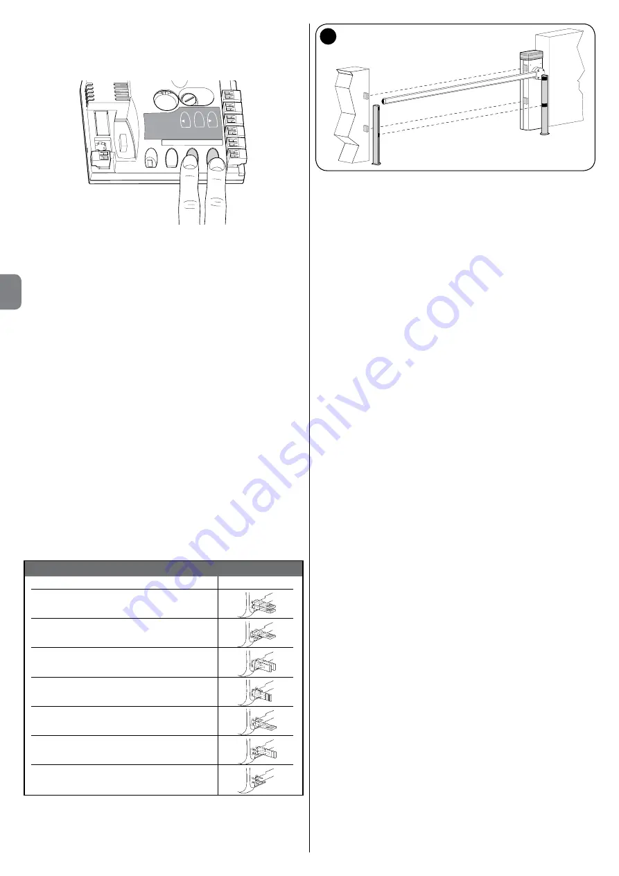
8.3.2 - Fotokomórki
System Bluebus umożliwia rozpoznawanie fotokomórek przez centralę poprzez
ustawienia specjalnych mostków (patrz
Tabela 13
), umożliwia również prawi-
dłowe realizowanie funkcji wykrywania przeszkód. Operacja adresowania musi
zostać wykonana zarówno w TX jak i w RX, poprzez ustawienie mostków w ten
sam sposób i sprawdzenie czy nie występują inne pary fotokomórek, którym
został przydzielony ten sam adres.
Fotokomórki mogą być instalowane jak pokazano na rys. A. Ważne – Po
za montowaniu lub odłączeniu fotokomórek należy wykonać fazę rozpoznawa-
nia urządzeń, jak opisano w paragrafie 4.4.
TABELA 13 - ADRESY FOTOKOMÓREK
Fotokomórka Mostki
FOTOKOMÓRKA
Fotokomórka wys. = 50 z zadziałaniem
podczas zamykania
FOTOKOMÓRKA II
Fotokomórka wys. = 100 z zadziałaniem
podczas zamykania
FOTOKOMÓRKA 1
Fotokomórka wys. = 50 z zadziałaniem
podczas zamykania
FOTOKOMÓRKA 1 II
(
*
)
Fotokomórka wys. = 100 z zadziałaniem
podczas zamykania
FOTOKOMÓRKA 2
Fotokomórka z zadziałaniem podczas
otwierania (zmienia na zamykanie)
FOTOKOMÓRKA 2 II
Fotokomórka z zadziałaniem podczas
otwierania (zmienia na zamykanie)
FOTOKOMÓRKA 3
Jedyna fotokomórka z zadziałaniem zarówno
podczas otwierania jak i zamykania
O
p
en
St
op
Se
t
Clo
se
Fuse 1AT
L1
L2
L3
L4
L5
L6
L7
L8
F
F
F 1 II
F 1 II
F II
F II
F 1
F 1
A
Możliwe jest zamontowanie fotokomórki TX lub RX wewnątrz skrzyni szlabanu,
w specjalnie przewidzianym do tego miejscu (
rys. 43
) .
Aby wymienić fotokomórkę, należy wykonać następujące czynności:
01.
Wyjąć kartę fotokomórki ze skrzynki, podważając ją płaskim śrubokrętem
(
rys. 43-a
) .
UWAGA!
- Nie wolno uszkodzić znajdujących się wewnątrz
elementów elektrycznych;
02.
Otworzyć puszkę fotokomórek, znajdującą się w skrzyni urządzeń dodat-
kowych (
rys. 43-b
);
03.
Zamocować kartę na dnie puszki (
rys. 43-c
);
04.
Wykonać otwór w gumowym panelu, przez który ma przejść kabel elek-
tryczny (
rys. 43-d
);
05.
Przełożyć kabel elektryczny i podłączyć go do zacisku fotokomórki (
rys.
43-e
);
06.
Zamknąć dno skrzynki pokrywą, uważając, aby zablokować gumę w
gnieździe (
rys. 43-f
);
07.
Zawiesić puszkę na obiektywie po stronie skrzyni, przesuwając ją z góry
na dół (
rys. 43-g
) .
8.3.3 - Przełącznik cyfrowy MOTB i czytnik zbliżeniowy kart MOMB
System Bluebus umożliwia podłączenie do 4 przełączników cyfrowych MOTB
lub 4 czytników kart zbliżeniowych MOMB.
Przełącznik MOTB umożliwia sterowanie automatyką poprzez wpisywanie na
klawiaturze jednej z wczytanych kombinacji numerycznych .
Czytnik MOMB umożliwia sterowanie automatyką poprzez przesunięcie wczy-
tanej uprzednio karty zbliżeniowej przed czujnikiem.
Te urządzenia są wyposażone w jednoznaczny kod, który jest rozpoznawany
i zapamiętywany podczas fazy rozpoznawania wszystkich podłączonych urzą-
dzeń(patrz paragraf 4.4).
W ten sposób zapobiega się wszelkim próbom podstępnej wymiany urzą-
dzenia; żadna osoba nieautoryzowana nie może sterować automatyką. Aby
uzyskać szczegółowe informacje należy przeczytać instrukcje obsługi MOTB
i MOMB .
8.3.4 - Wejście STOP
Funkcją wejścia STOP jest powodowanie natychmiastowego zatrzymania wyko-
nywanego manewru, po którym nastąpi krótka zmiana kierunku. Do tego wejścia
mogą być podłączane urządzenia z wyjściem ze stykiem normalnie otwartym
“NO”, normalnie zamkniętym “NC”, urządzenia optyczne lub urządzenia z wyj-
ściem o stałej oporności 8,2K
Ω
(listwy rezystancyjne) . Podczas fazy rozpoznawa-
nia centrala rozpoznaje rodzaj podłączonego urządzenia i powoduje zatrzymanie
ramienia (STOP) w przypadku wystąpienia jakiejkolwiek zmiany w stosunku do
rozpoznanego stanu. Z pomocą odpowiednich środków jest możliwe podłącze-
nie do wejścia STOP kilku urządzeń, również różnego typu:
• Można podłączyć równolegle ze sobą kilka urządzeń typu NO, bez ograni-
czenia ilości;
• Można podłączyć równolegle ze sobą kilka urządzeń typu NC, bez ograni-
czenia ilości;
• Można podłączyć równolegle ze sobą dwa urządzenia z wyjściem o stałej
oporności 8,2K
Ω
; w przypadku występowania więcej niż 2 urządzeń muszą
one zostać połączone “kaskadowo” z tylko jedną opornością końcową
8,2K
Ω
;
• Jest możliwa również kombinacja typu NO i NC, z równoległym połączeniem 2
styków. W tym przypadku należy połączyć szeregowo ze stykiem NC oporność
8,2K
Ω
; umożliwia to również kombinację 3 różnych urządzeń: NO, NC i 8,2K
Ω
.
Uwaga
– Jeżeli wejście STOP jest używane do podłączania urządzeń pełnią-
cych funkcje zabezpieczające, muszą to być urządzenia z wyjściem o stałej
oporności 8,2K
Ω
lub urządzenia optyczne OPTO SENSOR, które gwarantują
odpowiedni poziom zabezpieczenia przed uszkodzeniami .
Aby podłączyć urządzenie optyczne typu OPTO SENSOR należy wykonać
połączenia jak pokazano na
rys. 44
: maksymalny prąd dostarczany wynosi 40
mA przy 12 Vps.
8.4 - Diagnostyka
Niektóre urządzenia są przystosowane do wydawania sygnałów, z pomocą
których jest możliwe rozpoznawanie stanu funkcjonowania lub ewentualnych
anomalii .
8.4.1 - Sygnalizacje centrali sterującej
Diody weiść oraz przycisków znajdujących się w centrali sterującej (
rys. 45
)
wydają specjalne sygnały, zarówno, aby zasygnalizować zwykłe funkcjonowa-
nie jak i ewentualne anomalie . W
Tabelach 14
i
15
opisana jest przyczyna i
rozwiązanie, odnośnie każdego typu sygnalizacji.
Summary of Contents for S4BAR
Page 2: ......
Page 20: ......
Page 40: ......
Page 60: ......
Page 80: ......
Page 100: ......
Page 120: ......
Page 140: ......
Page 143: ...I I 1 A B C B 330 mm 2 179 5 mm 1146 mm 826 mm 4000 mm 3 b a d e f g h c...
Page 144: ...II II 5 A B C 1 2 4...
Page 145: ...III III 9 10 90 6 A C B 7 8 B A...
Page 146: ...IV IV 14 A B 15 A B 11 A B 12 13 A B...
Page 147: ...V V 16 A B 17 18...
Page 148: ...VI VI 20 180 21 C C A B 1cm 1cm 19 A C B...
Page 149: ...VII VII 22 23 26 L N 24 1 2 25...
Page 151: ...IX 30 A A B STOP 31 A B...
Page 152: ...X 32 A B C D STOP 33 A B 34...
Page 154: ...XII 300 200 700 500 39 300 200 700 500 150 40 41...
Page 155: ...a c d e b F2 F1 42 43 XIII...
Page 156: ...XIV 44 O pe n L1 L2 L3 L4 L5 L6 L7 L8 St op Se t Cl os e Fuse 1AT 45 f g...
Page 157: ......
Page 158: ......
Page 159: ......


