


EN
4
– English
3.4 - Barrier fixture
3.4.1 - If the support surface already exists
[
] The fixing surface must be perfectly smooth and flat. If the surface is in
concrete, it must be at least 0 .15 m thick, and must be adequately reinforced
with steel cages . The concrete volume must be greater than 0 .2 m
3
(a thick-
ness of 0 .25 m corresponds to 0 .8 m
2
; in other words equal to a square base
of approx. 0.9 m per side).
Anchoring to the concrete can be by means of 4 expansion bolts, fitted with 12
MA screws, which resist to a traction load of at least 400 kg. If the fixing surface
is in another material, the consistency must be checked and ensure that the 4
anchoring points can resist a load of at least 1000 kg. For fixture, use 12 MA
screws .
Proceed as follows:
01.
Open the barrier cabinet (
Fig. 4
);
02.
Place the barrier on the fixing surface and trace the points where the slots
are to be fixed (
Fig. 9
);
03.
Move the barrier and drill the traced surface points; then insert 4 expansion
bolts, not supplied (
Fig. 10
);
04.
Position the barrier correctly and secure by means of the relative nuts and
washers not supplied (
Fig. 11 - A, B
) .
3.4.2 - If the support surface does not exist
01.
Dig the foundation pit to house the foundation plate, (optional accessory) .
For the pit dimensions, refer to the specifications at point [
] of paragraph
3 .4 .1 .
02.
Prepare ducting for connection cables;
03.
On the foundation plate, fix the 4 bolts, placing a nut on the upper side of
each and one on the lower side of the plate .
Caution
– The lower nut must
be tightened down to the threaded section;
04.
Now cast the concrete, and before it sets, embed the foundation plate,
which must be positioned flush with the surface, parallel to the pole and
perfectly level (
Fig. 12
) . Wait for the concrete to set completely; in general,
at least 2 weeks;
05.
Remove the 4 upper nuts of the bolts;
06.
Open the barrier cabinet (
Fig. 4
);
07.
Position the barrier correctly and secure by means of the relative nuts and
wa shers supplied with the foundation plate e moved in point 04 (
Fig. 13 -
A, B
) .
3.5 - Pole installation
3.5.1 - Pole support assembly
01.
Insert the two plugs in the relative seats on the output motor shaft (
Fig.
14 - phase A
and
B
);
02.
Position the support on the output motor shaft, placing it in the “vertical
pole” position and tighten the relative screws and washers fully down to
secure (
Fig. 15
- phase A
and
B
);
03.
Position the pole cover and partially secure by means of the 4 screws sup-
plied (
Fig. 16
- phase A
and
B
) .
3.5.2 - Pole assembly
01.
Assemble the two joints (
Fig.
17
); each joint is made up of 2 half-shells and
8 self-tapping screws;
02.
Insert a joint in the first aluminium profile (
Fig.
18
– use a rubber mallet to
insert fully);
03.
Insert the joint support brackets on both sides of the profile slots (
Fig.
19
- phase A, B, C, D
), ensuring correct alignment of the brackets (use a
mallet to facilitate insertion);
04.
Repeat the procedure from point 01, to insert the remaining aluminium
profiles;
05.
Position the holes of the joint support brackets so that they are aligned
with the holes on the profiles;
06.
Secure the brackets with screws supplied for each joint (
Fig.
20
) .
07.
Lightly grease the aluminium guide on both sides (
Fig. 21
) .
08.
Perform this operation on both ends of the pole: insert the first part of
impact protection rubber in the slot, through to the end of the pole; then
insert the joint for the impact protection rubber (
Fig.
22
) and repeat with all
parts;
09.
Position the pole plug (
Fig.
23
);
A) the upper impact protection must be inserted by at least 2 cm;
the lower impact protection must protrude by 1 cm;
B) Insert the pole plug;
C) Secure the plug using the relative screw;
D) Push the upper impact protection towards the plug, inserting it
by 1 cm into the plug;
10.
On the opposite end to that with the plug, insert the pole support plates
(
Fig.
24
);
11.
Insert the pole assembly in the pole support shell, pushing it up to the end
and then tighten the 4 previously inserted support screws fully down .
3.6 - Manually releasing and locking the gearmotor
The gearmotor can be released manually on both sides of the barrier
as shown in Fig. 25:
01.
Rotate the key cover;
02.
Insert the key supplied and turn through 180° both clockwise and anti-
clockwise;
03.
To lock the gearmotor, rotate the key through a further 180° in the same
direction as before .
3.7 - Mechanical stop adjustment
01.
Release the gear motor manually (see paragraph
3.6
);
02.
Manually move the pole through a complete Opening and Closing manoeu-
vre;
03.
Then adjust the mechanical stop screws (
Fig. 26
and
27
) to align the pole
vertically and horizontally;
04.
Tighten down the nuts .
3.8 - Pole balancing
The pole needs to be balanced to establish the best balance between two fac-
tors: the weight of the pole and any accessories and the counterposed force of
the balancing spring . The latter individually guarantees balancing of the pole; if
this rises or lowers, proceed as described below .
01.
Release the gear motor manually (see paragraph
3.6
);
02.
Manually move the pole to mid-travel (45°) and leave stationary . Then
ensure that the pole remains still in position . If the pole tends to lift, reduce
the tension of the spring, if the pole tends to drop, increase the tension of
the spring . To modify spring tension, see point 04;
03.
Repeat point 02 positioning the pole also at approx. 20° and approx. 70°.
If the pole remains still in position, this means that balancing is correct; a
slight off balance is admissible, but the pole must never move significantly.
The off-balance value is only acceptable when the force required to move
the pole (measured at right angles to the pole and at 1 m from the rotation
axis) on Opening, Closing and in all other positions, does not exceed half
the value of the maximum torque (for this product, approx. 5 kg at 1 m).
04.
- If the pole is not correctly balanced; to balance move the pole to the
maximum opening position.
- Detach the balancing spring from its seat (
Fig. 28
) and move its anchor-
ing point towards the centre, to reduce spring tension, or outwards to
increase spring tension;
05.
Lock the gear motor (see paragraph
3.6
) .
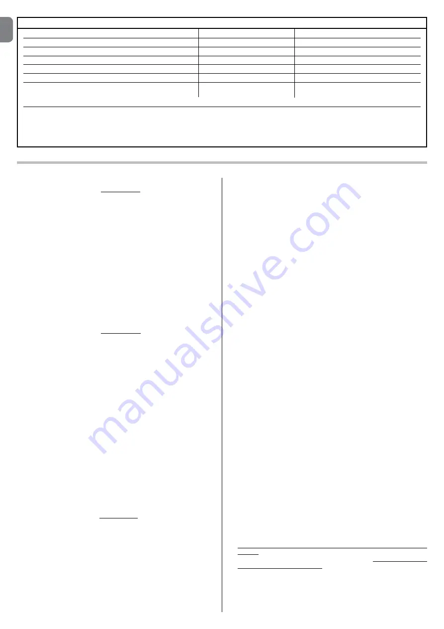
TABLE 3 - Technical specifications of electrical cables (Fig. 1)
Connection
Cable type
Maximum admissible length
A:
Mains POWER SUPPLY cable
cable 3 x 1,5 mm
2
30 m (
note 1
)
B:
Cable for BlueBus devices
cable 2 x 0,5 mm
2
30 m
C:
POLE LIGHTS
D:
KEY-OPERATED SELECTOR SWITCH cable
cables 4 x 0,25 mm
2
30 m (
note 2
)
E:
Built-in FLASHING LIGHT
OPTIONAL FLASHING LIGHT:
cable 2 x 0,5 mm
2
30 m
FLASHING LIGHT with aerial cable
RG58 shielded cable type
20 m (less than 5 m recommended)
IMPORTANT – To make the connection, programming of the FLASH output must be modified (see paragraph 6.2 - Table 7)
Note 1
– If the power cable is longer than 30 m, a cable with a larger cross-section is required (3 x 2.5 mm
2
) and safety earthing is necessary in the vicinity
of the automation .
Note 2
– If a MOMB transponder badge reader or MOTB digital keypad is used, a 2-wire cable is sufficient (2 x 0,5 mm
2
) .
CAUTION! – The cables used must be suited to the installation environment.
Summary of Contents for X-Bar
Page 2: ......
Page 3: ...I 1 A B D C D B 3 2 179 5 mm 300 mm 1146 mm 826 mm 3000 mm b a l d e c i g f h...
Page 4: ...II 5 A B C 4...
Page 5: ...III 9 10 90 6 A C B 7 8 B A...
Page 6: ...IV 14 A B 15 A B 11 A B 12 13 A B...
Page 7: ...V 18 17 16 A B...
Page 8: ...VI 20 21 OK O O 19 A B C D...
Page 9: ...VII 22 A 2cm 1cm 23 A B C D...
Page 10: ...VIII 24 26 27 180 25 C C A B...
Page 12: ...X Op en St op Se t Cl os e Fuse 1AT L1 L2 L3 L4 L5 L6 L7 L8 34 35 36 A A B...
Page 13: ...XI STOP 37 A B 38 A B C D...


