Roll Off Load Pin Installation
11
3.5
Routing Wiring
Because each truck is different, cable routing will be specific to the truck the system will be installed on.
Important
Plan a route that has little or no risk of pinching, stretching or melting the cables.
Use split loom on all exposed cable to protect in areas where damage could be an issue.
Wire tie any excess cable to the frame.
Note
For cab-over type truck cabs, all scale system cabling must run around the main pivot point of the cab-over
hinge. For conventional cabs, look for cab access grommets in the flooring near the driver seat area.
For ease of connection, label the cables used in installation prior to threading through the hole into the cab.
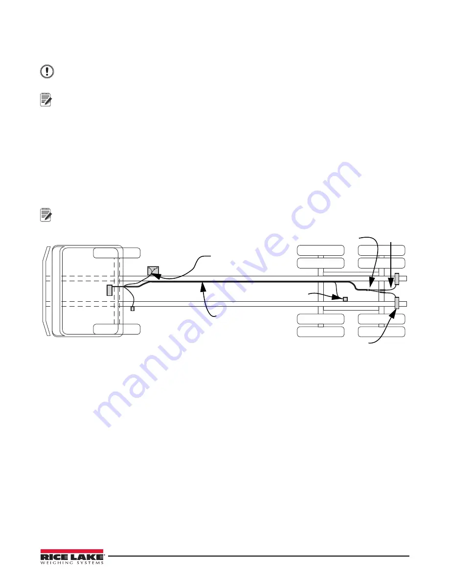
1. Connect 6
’
cables to the load pins.
2. Connect the load pin cables to the Y cable.
3. Connect 15
’
cable and 3
’
cable (if necessary) to the Y cable.
4. Route the 15
’
cable along frame to the indicator through access hole in the cab.
5. Wire tie the cable to the frame approximately every 18 inches.
6. Follow the same route with the inclinometer cable.
7. Route the power cable from the battery to the indicator location.
Load
Pins
Inclinometer
Y Cable
Battery
Transducer
Indicator
Power Cable
15
’
Cable
6
’
Cable
Note
Connecting wiring to the indicator is shown in Section 3.6.
Figure 3-10. Wiring Diagram


