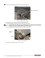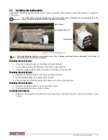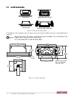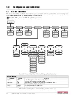
Roll Off Load Pin Installation
13
3.6.1
Electrical Wiring and Data Connections
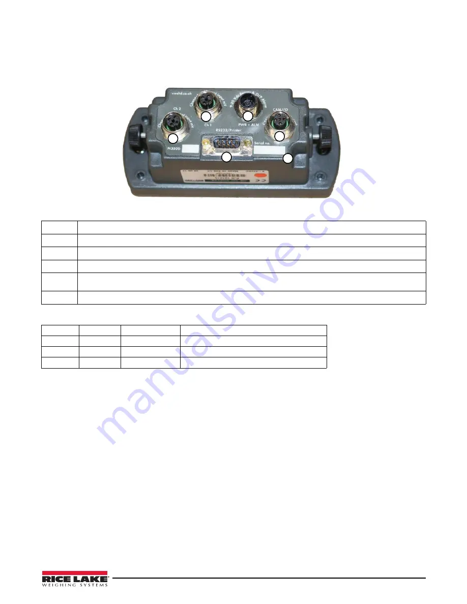
The indicator is fitted with one Power and one Input Channel connector as standard. CANbus, Channel 2 and RS-232 are optional.
Full connector options are shown below.
1
3
2
4
5
6
12B1D4FB
T
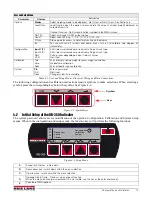
Figure 3-13. Rear Panel Identification and Bulkhead Connectors
1
Input Channel 1, Max +/-39.0625 milli-Volts (Hydraulic Pressure Transducer)
2
Input Channel 2, Max +/-39.0625 milli-Volts (Load Pin Connection)
3
Power Input
4
CANbus digital input & output (Inclinometer Connection)
5
RS-232 output for printers and data capture devices (pin 9 = vehicle volts, pin 5 = ground, pin = 2 transmit, pin 3 =
receive)
6
Alpha-numeric unique indicator serial number, also appears on
power-on
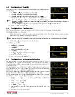
POWER & ALARM, socket is MALE – CON 1 on PCB
Pin 1
BROWN
Vehicle voltage
Supply 12V (LCV) or 24V (MCV & HGV)
Pin 2
WHITE
Output 1
12V or 24V
Pin 3
BLUE
Ground
Ground 0 Volts (common)
Pin 4
BLACK
Output 2
12V or 24V
3.7
Final Installation
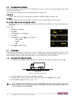
1. Reinstall the fenders.
2. Test the hoist to make sure none of the cables at risk of being pinched, stretched or cut when it is raised and
lowered.
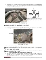
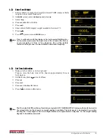
3. Test the hoist to make sure the scale reads positively with applied weight. If positive weight is not
displayed, it is possible that the load pins or a load pin are not in the correct position and reading
backwards. Pin position can be changed by rotating 180 degrees.


