background image

18

LoadRunner™ Series Installation & Service Manual

4.6

Configuration of Modes

With the inclinometer option turned on, the inclinometer screen is visible by switching display screens when 
pressing the menu button.

The display screen will toggle between the following when configured for:

Gross Mode:

Toggles between gross only weight display, inclinometer standard display and menu mode

Net Mode:

Toggles between net only weight display, inclinometer with net weight display and menu mode

Net and Gross Mode (factory recommended setting):

Toggles between net only weight display, gross only weight display, inclinometer with net weight display and 
menu mode.

To set mode:

1. In 

MENU

, select 

Options

.

2. Press 

(OK).

3. In 

OPTIONS

 menu, select 

Modes

.

4. Press 

(OK).

5. In 

MODES

 menu, press 

 to toggle between 

NET & GROSS

GROSS

NET

6. Press 

 to confirm setting.

4.7

Calibration

Calibration requires the use of a truck scale in order to calibrate the system. First determine the empty vehicle 
weight or tare weight of the truck. Once the tare and zero calibration are performed, load the vehicle as close to its 
legal maximum limit as possible to determine the span or net weight value used for calibration.

4.7.1

Calculating the SPAN (Net Weight)

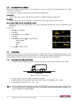
1. To determine actual 

TARE

 weight, drive the empty vehicle onto a truck scale and note the total weight. 

Truck Scale

Figure 4-4. Vehicle on Truck Scale

2. Load the vehicle as close to its legal maximum as possible.

3. Weigh the loaded vehicle, using the same truck scale, and record the 

GROSS

 vehicle weight.

4. Calculate 

NET

 weight using: 

Gross - Tare = Net

.

Note

Prior to calibration, with the display in the Inclinometer/Net Weight or Inclinometer mode raise the body clear of 
the chassis (the factory recommendation is three or four degrees). Record the bubble indication setting for use 
on span calibration and normal weighing. 

Summary of Contents for LoadRunner Series

Page 1: ...ustin Ft Worth NicolScales com 800 225 8181 Contact Us Nicol Scales Measurement is an ISO Accredited Calibration Company that has provided calibration repair and sales of all types of weighing and mea...

Page 2: ...LoadRunner Series OnBoard Weighing System for Roll Off Trucks Installation Service Manual 160913...

Page 3: ......

Page 4: ...4 0 Configuration and Calibration 14 4 1 User and Setup Menu 14 4 2 Initial Setup of the OB 350 Indicator 15 4 2 1 Initial Password Entry and Clock Setup 16 4 2 2 Configuration of Input Channels 16 4...

Page 5: ...ii On Board Weighing Installation Service Manual Rice Lake continually offers web based video training on a growing selection of product related topics at no cost Visit www ricelake com webinars...

Page 6: ...moved Indicates a potentially hazardous situation that if not avoided may result in minor or moderate injury Indicates information about procedures that if not observed could result in damage to equip...

Page 7: ...must be connected or capped during painting or undercoating The instructions outlined herein are designed to ensure that a correct installation will provide maximum safety optimum system performance a...

Page 8: ...and accurate 2 1 Onboard Roll Off Kit Parts 1 2 3 9 7 Battery 4 5 6 8 10 Figure 2 1 Onboard System Roll Off Kit Illustration Table 2 1 Onboard System Roll Off Kit Parts List Item No Part No Descripti...

Page 9: ...steel nickel plated for corrosion resistance tted with an M12 commercial vehicle class connector 11 8 300 mm 2 49 mm 0 79 20 mm 5 5 142 mm 0 79 20 mm 0 5 14 mm Orientation and Anti rotation Reaction...

Page 10: ...9 1 6 1 8 S A E 1 2 3 3 m m 16 5 M if four core cable with a M12 fully moulded male connector Material Stainless Steel Sealing Fully welded to IP68 Figure 2 4 Oil Pressure Transducer PN 131211 2 4 Rol...

Page 11: ...required to gain free and clear access to the pivots 2 Use jacks or a forklift to support the rear of the hoist chassis and maintain its position alignment while the pivot pins are being replaced 3 R...

Page 12: ...cure with bolt Pin should go in from the top and be vertical Use a small square to ensure the bolt is precisely vertical Collar and bolt Figure 3 4 Install Collar and Bolt 11 Tack weld the collar to t...

Page 13: ...with the hole in the collar 1 2 20 x 5 Screw Load Pin Important Do NOT strike the load cell directly as it may cause damage to the load cell Use a wood block or similar material to cushion the load c...

Page 14: ...type of truck frame the unit is being mounted to Mounting Bracket Option 1 1 Align the mounting bracket to the frame and mark the holes 2 Set the bracket aside and drill holes in the frame where mark...

Page 15: ...ssure Transducer 1 Remove the hose where the transducer is to be installed 2 Install a tee fitting to connect the hose to the hydraulic valve 3 Insert a reducer if required 9 16 straight thread with O...

Page 16: ...rommets in the flooring near the driver seat area For ease of connection label the cables used in installation prior to threading through the hole into the cab 1 Connect 6 cables to the load pins 2 Co...

Page 17: ...71 in 18 mm 4 00 in 100 5 mm 2 50 in 62 5 mm 5 71 in 145 mm 1 73 in 44 mm 5 71 in 145 mm 4 80 in 122 mm 1 57 in 40 mm 2 32 in 59 mm 3 54 in 90 mm 3 54 in 90 mm 0 25 in 6 5 mm holes for u brackets 0 15...

Page 18: ...9 vehicle volts pin 5 ground pin 2 transmit pin 3 receive 6 Alpha numeric unique indicator serial number also appears on power on POWER ALARM socket is MALE CON 1 on PCB Pin 1 BROWN Vehicle voltage S...

Page 19: ...ck Net Gross Net Gross ON OFF Chan Load Z Func Keyboard Inhibit Keyboard Printer Printer CSV Data Printer G PVWS None Format 1 4 Scoreboard Net 4 Gross 4 5 G PVWS BA4840 The default password is 0350 K...

Page 20: ...ptions Options Modes Select weighing mode to be displayed Net Gross or Net Gross See Section 4 6 Load Chan Load function gives the option to accumulate the amount of load weight delivered or collected...

Page 21: ...PIN 10 Press to back up to MENU 11 To Set PIN select PIN press OK and repeat 2 6 12 Use or to scroll to Clock 13 Press OK 14 Select the edit key to modify time military and date international Press or...

Page 22: ...ibit zero De activate operator zero functionality To set the Zero Function 1 In MENU select Options 2 Press OK 3 In OPTIONS menu select Z Func 4 Press OK 5 Use or to scroll to desired option 6 Press t...

Page 23: ...onfirm setting 4 7 Calibration Calibration requires the use of a truck scale in order to calibrate the system First determine the empty vehicle weight or tare weight of the truck Once the tare and zer...

Page 24: ...or four degrees Record the bubble indication setting for use on span calibration and normal weighing Note 4 7 3 Set Zero Calibration lb lb 1 Make sure the vehicle is on level ground Tippers raise the...

Page 25: ...ubtract the TARE weight from the GROSS weight to give the SPAN NET weight 31900 12500 19400 kg SPAN NET PAYLOAD If the vehicle is atipper raise the body clear ofthechassis 4 In CAL menu press to Span...

Page 26: ...ransportation DOT state and local regulations the recommended standards and practices of the Society of Automotive Engineers SAE standards of the American Welding Society AWS and the recommendations o...

Page 27: ...ble run 5 4 2 Connections Rice Lake Weighing Systems uses special connectors which do not corrode and can withstand extremely cold conditions When aluminum connectors are present especially in environ...

Page 28: ...improper testing RLWS shall be the sole judge of all alleged non conformities Such equipment has not been modified altered or changed by any person other than RLWS or its duly authorized repair agents...

Page 29: ...24 LoadRunner Series Installation Service Manual...

Page 30: ......

Page 31: ...54868 USA U S 800 472 6703 Canada Mexico 800 321 6703 International 715 234 9171 Europe 31 0 88 2349171 www ricelake com www ricelake mx www ricelake eu www ricelake co in m ricelake com Rice Lake Wei...

Reviews: