background image

8

RoughDeck Low Profile Floor Scale Installation Manual

3.0

Adjustments and Calibration

3.1

Mechanical Adjustments

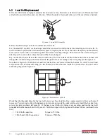
To accommodate minor floor unevenness, scale feet can be used to adjust scale height up or down a fraction of an 

inch. Adjust the feet by hand (lift the scale corner slightly with a pry bar) until all feet are contacting the floor 

equally. No jam nuts are supplied for locking the feet, as there is a slight decrease in accuracy when jam nuts are 

tightened. If the application requires the feet to be secured, use Teflon tape or Loctite.

CAUTION

When adjusting scale feet, use care to prevent scale foot from bottoming out against the underside of the 
load cell. Also, the foot stem may be damaged by bending or stripping threads if extended beyond the 
maximum height adjustment.

When height adjustments are complete, recheck level of the deck with a spirit level. The deck must be level within 

1/4".

3.2

Corner Correction

All assembled 

RoughDeck

 scales are delivered 

with the junction box corner-trimmed. Corner 

trimming is only necessary after replacing a load 

cell.

JP4

JP2

PT4

PT3

JP3

PT1

EXP

PT2

JP1

1

CELL4

1

CELL1

1

CELL3

1

CELL2

IND

-EX

-SI

SHD

+SI

+EX

M

R

N

I

-SI

S2C

I

A

G

+EX

+SI

-SI

SHD

-EX

I

S

G

A
L

T

+SI

M

S

I

N

L

T

R

+EX

-EX

-SI

SHD

+SI

+EX

+SI

-EX

-SI

SHD

-EX

SHD

+SE

-SE

+EX

Potentiometers

Jumper Locations
JP1 and JP2
Shaded

Jumper Locations
JP3 and JP4
Shaded

Potentiometers

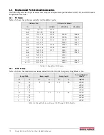
Figure 3-1. Trim Potentiometers

To calibrate the scale, the output from each load 

cell must be matched by adjusting the signals 

with potentiometers at the junction box. This 

process is known as trimming.
Remove the junction box cover and identify the 

correct load cell terminal corresponding to each 

corner (labeled CELL 1, CELL 2, and so on). 

See Figure 4-4 on page 11 for scale deck corner 

numbering.
The indicator must be connected and calibrated 

approximately, but it need not indicate the exact 

weight value. A test weight will be required. The 

recommended test weight for all 

RoughDeck


models is 25% of scale capacity: for example, 

500 lbs for 2K-lb models, 5000 lb for 20K-lb 

models.
With no weight on the scale, zero the indicator. 

Then turn all four potentiometers (shaded areas 

of Figure ) to increase the reading until a clicking sound is heard from each potentiometer. This ensures the 

maximum signal from each load cell.
With all potentiometers at full signal, place the test weight over one corner and record the indicated weight. Repeat 

the process for each of the other three corners. The load cell with the lowest corner reading will be used as a 

reference point and will not be trimmed.
Next, place the test weight over one of the other three corners and use that cell’s potentiometer to adjust the cell 

output down to the reference cell output. Repeat this procedure with the other two high corners.
Adjustments are somewhat interactive, and adjusting the three higher outputs may affect the reference cell output, 

especially in smaller scale decks. Rezero the indicator and repeat the test until all corners read within ±.1% of the 

test weight used.

3.3

Calibration Procedure

Refer to the indicator manual to determine correct calibration procedures.
It is recommended that the scale be “exercised” before calibration to be certain that everything is seated. Load the 

scale to near capacity two or three times. 
Then, with no load on the scale, place the indicator in its calibration mode and perform a zero calibration. Now 

place test weights on the platform equal to 70% - 80% of the scale’s capacity. If several weights are used, they 

should be evenly distributed around the platform. Perform a span calibration. 
Remove the test weights and check the zero reading. Repeat the calibration process if necessary.

Summary of Contents for RoughDeck

Page 1: ...ustin Ft Worth NicolScales com 800 225 8181 Contact Us Nicol Scales Measurement is an ISO Accredited Calibration Company that has provided calibration repair and sales of all types of weighing and mea...

Page 2: ...RoughDeck Low Profile Floor Scale HP HP H HC and ROUGH N READY Installation Manual PN 66662 Rev F...

Page 3: ......

Page 4: ...e 8 4 0 Service Information 9 4 1 Troubleshooting Guide 9 4 2 Periodic Maintenance 9 4 3 Load Cell Replacement 10 4 3 1 Load Cell Wiring to Junction Box 11 4 4 Replacement Parts List and Accessories 1...

Page 5: ...i RoughDeck Low Profile Floor Scale Installation Manual Rice Lake continually offers web based video training on a growing selection of product related topics at no cost Visit www ricelake com webinar...

Page 6: ...stom frames for pit installations and access ramps for all sizes and models of the RoughDeck Decks designed for use in pits can be ordered with holes drilled in the deck directly above each foot for a...

Page 7: ...use this product if any of the components are cracked DO NOT exceed the rated load limit of the unit DO NOT make alterations or modifications to the unit DO NOT remove or obscure warning labels DO NO...

Page 8: ...In operation the scale must be level within 1 4 inch Either choose a site where the floor is close to this standard to avoid excessive shimming or modify the floor at the chosen site to meet this stan...

Page 9: ...oor check the deck with the spirit level to be sure the scale is within 1 4 inch of level 2 4 2 Mounting Plate Installation For permanent applications the scale should be secured to the floor to preve...

Page 10: ...SI SHD EX I S G A L T SI M S I N L T R EX EX SI SHD SI EX SI EX SI SHD EX SHD SE SE EX Figure 2 3 Junction Box Indicator Terminal 2 5 1 Electrical Interface to Indicator Twenty feet of 6 wire cable to...

Page 11: ...itable poured concrete foundation according to standard construction practices COVER PLATE 1 24 SLOPE LOAD CELL CUP FOOT ASSEMBL Y GROUT Figure 2 5 Section Showing Installed Heavy Capacity HP H Model...

Page 12: ...cessary Access ramps can only be attached to the scale on one of the two scale sides that are perpendicular to the longitudinal axis of the load cells For example the scale shown in Figure 2 5 could h...

Page 13: ...page 11 for scale deck corner numbering The indicator must be connected and calibrated approximately but it need not indicate the exact weight value A test weight will be required The recommended test...

Page 14: ...Consistently high or low weights Indicator not properly adjusted to zero Zero the indicator according to indicator manual Platform binding Obtain adequate clearance for free platform movement Indicato...

Page 15: ...where they are to be installed Thread the cable from each load cell through the conduit tubing in the frame and into the junction box according to the wiring diagram in Figure 4 2 Note that in Figure...

Page 16: ...ation is necessary after load cell replacement Follow instruction in Section 3 2 and Section 3 3 on page 8 4 3 1 Load Cell Wiring to Junction Box The four load cells are each wired to their respective...

Page 17: ...8765 39596 39609 4 x 6 1 22 x 1 83 18767 39597 39610 4 x 7 1 22 x 2 13 39598 39611 5 x 5 1 53 x 1 53 18763 39599 39612 5 x 6 1 53 x 1 83 18769 39600 5 x 7 1 53 x 2 13 18771 39601 39614 6 x 6 1 83 x 1...

Page 18: ...0k 2 5 x 2 5 76 x 76 18757 3 x 3 92 x 92 18759 4 x 4 1 22 x 1 22 18761 39595 39608 4 x 5 1 22 x 1 53 18765 39596 39609 4 x 6 1 22 x 1 83 18767 39597 39610 4 x 7 1 22 x 2 13 39598 39611 5 x 5 1 53 x 1...

Page 19: ...confirms that the nonconformity actually exists and was not caused by accident misuse neglect alteration improper installation improper repair or improper testing RLWS shall be the sole judge of all...

Page 20: ......

Page 21: ...USA U S 800 472 6703 Canada Mexico 800 321 6703 International 715 234 9171 Europe 31 0 26 472 1319 www ricelake com www ricelake mx www ricelake eu www ricelake co in m ricelake com Rice Lake Weighing...

Reviews: