10
RoughDeck Low Profile Floor Scale Installation Manual
4.3
Load Cell Replacement
Lift scale with chains and proper spreader bar and remove foot, then remove defective load cell. Disconnect load
cell cable from junction box and cut cable ties. When the cable is freed, pull cable out of the scale frame channels.
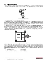
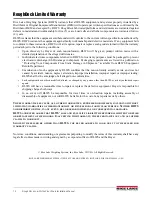
Figure 4-1. Load Cell Assembly
Follow the directions given below to install new load cells.
For Canadian HC models, overload stops should be loosened two full turns before installing new load cells. To
reset overload stops after load cell installation, place a weight equal to 25% of the load cell capacity on the affected
scale corner. Screw in the overload stop until the indicator reading changes. Then back off the overload stop 1/6
turn. Repeat for each corner where the load cell has been changed.
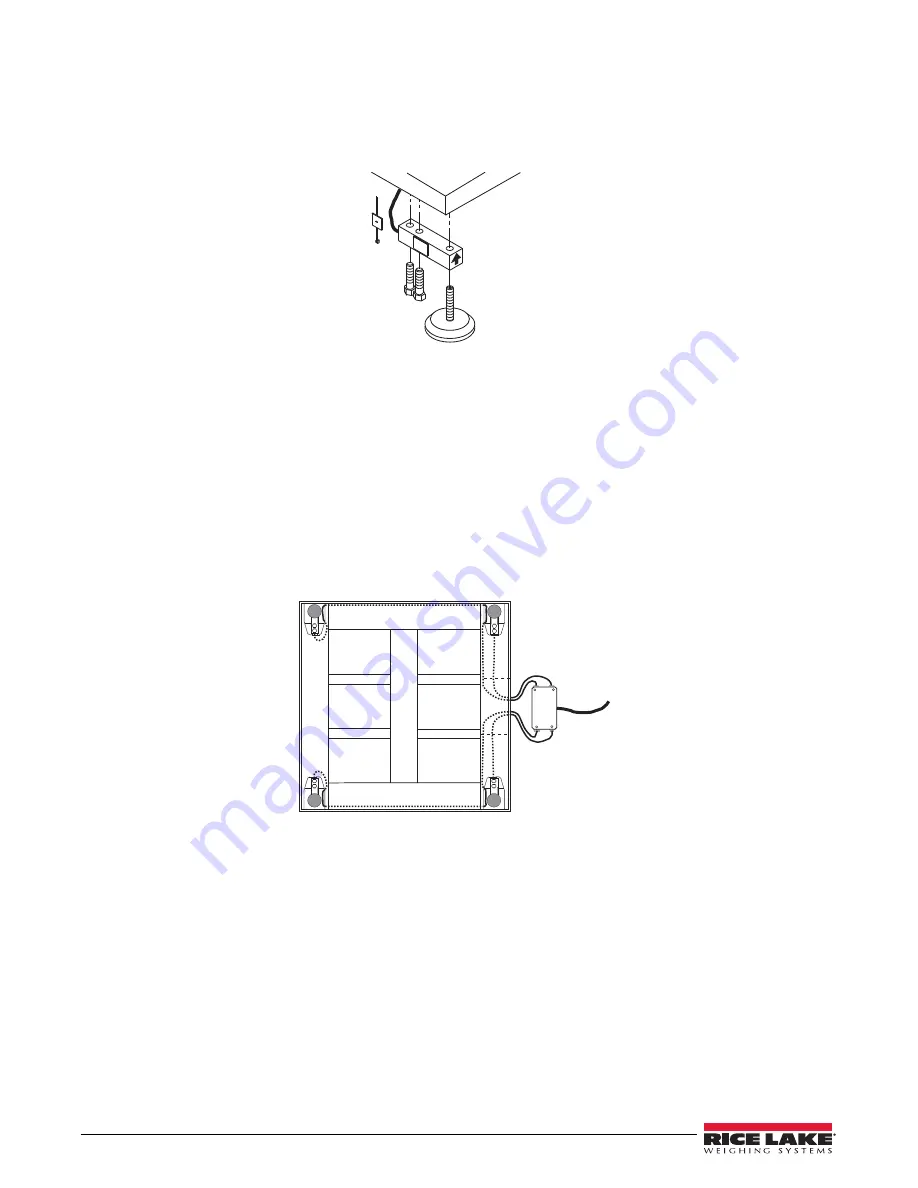
Lay out the four load cells near the corners where they are to be installed. Thread the cable from each load cell
through the conduit tubing in the frame and into the junction box according to the wiring diagram in Figure 4-2.
Note that in Figure 4-2 both the scale and the junction box are viewed from the bottom. To verify correct load
cell/junction box terminal matching, see the numbers on the terminals inside the junction box and the corner
numbering diagram in Figure 4-4.
CELL
4
CELL
3
CELL
2
CELL
1
1
4
2
3
Figure 4-2. Bottom View of Scale
Check that the threaded holes for the load cell screws are free of debris. Use compressed air to blow out holes if
necessary. Position load cells with alignment arrows point up toward the deck and loosely install the hex head cap
screws provided, as shown in Figure 4-1. If the base is used with a pit frame or access ramp, position the load cell
to maintain the dimension shown in Figure 4-3. With the torque wrench, tighten all bolts as follows (outboard bolts
first):
•
2K–10K-lb capacities:
Torque to 75 ft-lbs.
•
20K-lb and 30K-lb capacities:
Torque to 250ft-lbs.


