Rev. 1 - 05/10/2021
OPERATING MANUAL
OPERATING MANUAL
EN
EN
52/56
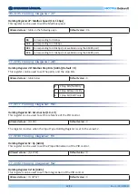
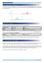
The system status can be displayed through the LED on the driver plate
(see par. 9.6). In the following figure on the right the blinking LED is shown.
18.3 Blinking LED - Alarm description
In the following table, the alarms and the values stored in the related Modbus
Input Register 10 and Input
Register 17 are indicated.
18.2 Modbus registers - Alarm description
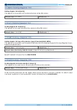
The Driver is NOT protected against a very high-power supply voltage.
A very low power supply voltage during the motor running could damage Driver.
WARNING
WARNING
1 sec.
*
After loss of synchronism, the auto-restarting condition is activated for 1.35 kW and 2.6 kW drivers.
In case of loss of synchronism for 5.5 kW drivers, the blocking condition is activated after five failed attempts
and the fan must be reset manually.
Check the blocking reasons and close the gate in case of opposite flow.
A l a r m
1
Alarm 2 Description
Actions
Type
0
0
Default operation – No Errors
No Actions
ALARM 1
1
0
Memory error
Blocking condition
ALARM 2
2
0
Short Circuit
Blocking condition
ALARM 3
3
0
Loss of synchronism
Auto-restarting condition
*
ALARM 4
4
1
Input Voltage outside range (only with motor
stopped)
Auto-restarting condition
ALARM 4
4
32
BUS overvoltage (instantaneous measure-
ment)
Auto-restarting condition
ALARM 4
4
33
BUS undervoltage (instantaneous measure-
ment)
Auto-restarting condition
ALARM 4
4
34
Input relay not closed
Auto-restarting condition
ALARM 4
4
49
Missing phase – U cable disconnected
Blocking condition
ALARM 4
4
50
Missing phase – V cable disconnected
Blocking condition
ALARM 4
4
51
Missing phase – W cable disconnected
Blocking condition
ALARM 4
4
52
High starting current
Auto-restarting condition
ALARM 4
4
113
Overtemperature
Auto-restarting condition
ALARM 4
4
255
Loss of communication
Blocking condition
ALARM 4


