Rev. 1 - 05/10/2021
OPERATING MANUAL
OPERATING MANUAL
EN
EN
53/56
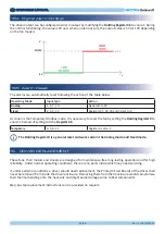
The driver output can be configured as Alarm output by modifying the
Holding Register 46 to value 1. During
the normal functioning, the value is 0V and, when an alarm occurs, the output value is 5V (or 10V depending
on the fan model).
18.4 Digital Alarm Output
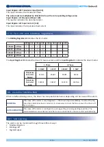
The alarms are automatically reset following the action of the table below:
18.5 Alarm Reset
Operating Mode
Input Type
Action
Analog
1, 4, 7, 10
Signal set to 0V
Fixed
2, 6, 9, 12
Registers 21, 39, 30 and 50 set to 0
As conerns the Temporary Modbus mode, it is necessary to reset the fan by setting the
Holding Register 0 to
value=1 instead of setting to 0 the
Register 66.
Temporary
0, 5, 8, 11
Register 0 set to 1
The Holding Register 0 is a general reset and works also in the Analog mode and Fixed mode.
5V/10V
0V
V
s
19. DRIVER REPLACEMENT
These fans, their motors and drivers are designed for maintenance-free long-lasting operation and for high
reliability. Under normal operating conditions, there are no parts inside which may need servicing.
If, under extreme conditions, a driver should need replacement, the Printed Circuit Boards of the driver shall
never be removed from inside the driver enclosure. Removing them from their enclosure would compromise
their thermal bonding onto the heat-sink and might easily damage some critical components.
Step-by-step replacement instructions can be provided on request.


