SV850 SAFETach™ III Incremental Encoder
5
Rev: 001
ELECTRICAL**
A. Operating Power (Vin)
1. Volts ........................5-24 VDC
2. Current ...................100mA, nominal, no load
B. Output Format
1. 2O/ & Comp ...........A, A–, B, B– (differential line driver)
2. Marker ....................1/Rev, Z, Z–
C. Signal Type .................Incremental, Square Wave, 50 ±10%
Duty Cycle.
D. Direction Sensing .......O/ A leads O/ B for CW rotation as viewed
from the
..................................
back of the tach looking at the
non-drive end of the
.................................
motor.
E. Phase Sep. .................15% minimum
F. Frequency Range .......@5V, @1m cable, 250 kHz Max
.................................
@24V, @300m cable, #8 output, 45 kHz Max
G. PPR .............................4-50000***
H. Line Driver Specs .......See table
I. Connectors .................Industrial Connector or terminal box
J. LED Indicator ...............GREEN: power on, unit ok.
................................
RED: alarm on
.................................
ORANGE: wiring fault (Thermal Overload; Under-
................................
voltage)
MECHANICAL
A. Rotor Inertia:...............0.12-0.41 Oz. In. Sec.
2
B. Acceleration:...............5000 RPM/Sec. Max.
C. Speed: .........................6000 RPM Max.****
D. Weight: ........................2-3 lbs [0.9kg to 1.36kg].
E. Sensor to Rotor
Air Gap (nominal):.......0.045” [1.14mm]
Tolerance: ...................-0.030”/+0.015” [-0.76mm/+0.38]
F. Rotor Axial Tolerance .±0.050” [±1.27mm]
ENVIRONMENTAL
Solid cast aluminum stator and rotor
Fully potted electronics, protected against oil and water spray
Use “W” cable option on IP66/67 applications
V-Ring seals provided on through shaft covers
Operating Temperature: ........... -40 to 100°C, 0-100% condensing humidity
Vibration:
18 g’s
Shock:
1 meter drop test
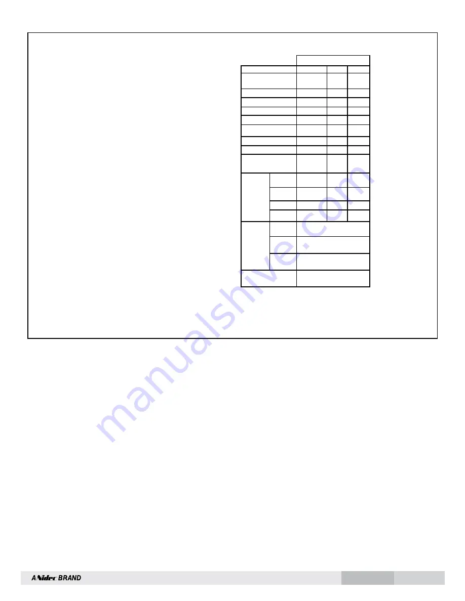
LINE DRIVER OPTIONS
SPECIFICATIONS
* Alarm not available on connector option “G” (Northstar
TM
compatible pinout)
** Electrical specifications for SAFETach III model (rev BA or later), consult Nidec
Industrial Solutions for earlier model specifications.
***(PPR) Standard maximum PPR is 5000. Consult Factory with your application
for PPRs up to 50,000.
**** (Speed) Maximum RPM may be limited for PPR > 2,500. Consult Factory with
your application.
LINE DRIVER OPTIONS
Electrical Specifications
6
9
Units
Input Voltage
5-24
5-24
VDC
Nom Output Voltage
5-24
5
VDC
Line Driver
7272
7272
Output Resistance Typ
13
13
ohms
Maximum Peak Current
1500
1500
mA
Maximum Average
Current
120
120
mA
Voh Typ
V
IN
-1
V
IN
-1
VDC
Vol Typ
0.5
0.5
VDC
Cable Drive Capacity
1000’ @ 5V
500’ @ 12V
200’ @ 24V
1000’
feet
Protection
Reverse
Voltage
yes
yes
Short
Circuit
yes
yes
Transient
yes
yes
Power to A,
Gnd to A/
yes
yes
Alarm
+V(out)
Output voltage equal to input
voltage.
Alarm*
Open collector, normally off, goes
low on alarm,
sink 100mA max, 50VDC max
LED
Green=power on, Red=Alarm
Orange=Wiring Error (Thermal
Overload; Under-voltage)
Marker
One per revolution. Pulse width
approximately 2
° (1/128 of a
revolution)


