


XR67
1
8 9 0 1 E . P L E A S A N T VA L L E Y R O A D • I N D E P E N D E N C E , O H I O 4 4 1 3 1 - 5 5 0 8
T E L E P H O N E : ( 1 ) 2 1 6 - 6 4 2 - 1 2 3 0 • FA X : ( 1 ) 2 1 6 - 6 4 2 - 6 0 3 7
E - M A I L : t a c h s @ n i d e c - a v t r o n . c o m • W E B : w w w. a v t r o n e n c o d e r s . c o m
Nidec-Avtron Makes the Most Reliable Encoders in the World
Encoder Instructions
MODEL
XR67 SMARTSafe
™
6 3/4” C-FACE MOUNT
MODULAR FOR HAZARDOUS
APPLICATIONS
DESCRIPTION
The Avtron XR67, SMARTSafe™ is a modular, two piece incremental
encoder for hazardous atmosphere applications (also known as a
tachometer or rotary pulse generator). It provides a two phase, A Quad
B frequency (pulse) output, with complements. The XR67 mounts on a
6.75” Face.
CAUTION
The XR67 is designed for use in hazardous applications
which require protection from gas or dust ignition for
safe operation. Proper selection, wiring and installation
procedures are essential to ensuring safe conditions.
Because the XR67 is modular, there are no bearings or couplings
required. This, combined with the latest magneto resistive (MR)
sensor technology, allows the XR67 to provide superior mechanical
performance and increased reliability.
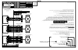
An Avtron XR67 can be configured with one or two independent
outputs. Each output has six signals: (A, B) 90° out of phase, with
complements (A–, B–). A marker pulse with complement (Z, Z–) is also
provided.
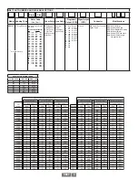
Output resolution on the XR67 is determined by the sensor only.
Unlike older models, any PPRs can be mixed and matched. Selection
of the rotor is based only on the shaft mounting requirements (and not
PPR).
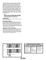
ADAPTIVE ELECTRONICS
A perfect duty cycle consists of a waveform whose “high” and “low”
conditions are of the same duration (50%/50%). It is possible over time
for the duty cycle and edge separation to change due to component
drift, temperature changes, or mechanical wear. The Adaptive
Electronics extend the life of the XR67 by constantly monitoring and
correcting duty cycle and edge separation over time.
INSTALLATION
WARNING
Installation should be performed only by qualified
personnel. Safety precautions must be taken to ensure
machinery cannot rotate and all sources of power are
removed during installation.
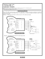
Refer to the following attached installation drawings for
installation information appropriate for specific hazardous
locations:
D52352: ATEX / IECEx Zone 1, 21
D52353: ATEX / IECEx Zone 2, 22
D52354: US and Canada Class I Division 1 Encoder
D52355: US and Canada Class I Division 2
NOTE:
The equipment is intended for a fixed installation and
should be mounted so as to avoid electrostatic charging.
The XR67 is not considered as a safety device and is not
suitable for connection into a safety system.
The XR67 construction materials contain no more than 7.5% in total
by mass of magnesium, titanium and zirconium. These materials are
not considered as able to trigger an explosion in normal operating
modes. These materials are not known to react with any explosive
atmospheres to which the XR67 may be subject. It is however the
responsibility of the end user to ensure that the XR67 is selected
correctly for the potentially explosive atmosphere in which the
equipment is to be put into service.
The XR67 installation is similar to AV67. Installation and removal
videos for the AV56/67/85/115 are available on Avtron’s web site.
Refer to the back page of these instructions for outline and mounting
dimensions. The motor must comply with 1998 NEMA MG 1, section 4,
for tolerances on diameters and runout for shafts and accessory faces.
Axial float or endplay plus rotor location toleration must be less than
±0.050”.
In preparation for installing the Model XR67 encoder, it is first
necessary to clean both the accessory motor shaft and the mounting
face. These surfaces must be inspected and any paint, burrs, or other
surface imperfections removed.
Installation procedures should be performed only by qualified
personnel. Safety precautions must be taken to ensure machinery
cannot rotate and all sources of power are removed during
installation.
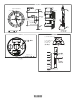
ROTOR INSTALLATION
The motor shaft must project at least 0.88” from the motor recessed
pilot. For set screw rotors only: Apply anti-seize compound to the motor
shaft. For all rotors: Slide the rotor onto the shaft with the marking
“Motor side” facing in, (toward the motor face). The rotor centerline
must match the sensor centerline. To accomplish this, use the rotor
locating gauge (A28504) and slide the rotor onto the shaft until it is in
the proper position as shown in Figure 1. If a guage is not available,
use the stator housing alignment grooves as shown in Figure 3.
STANDARD CAM SCREW ROTOR INSTALLATION
Turn the cam screws of the rotor in the directions shown on the rotor to
engage the cams. Tighten to 50-60 in-lb [5.6 - 6.8 N-m] (See Figure 2)
using the 3mm hex wrench. Total cam screw rotation will be less than
one turn.
CAUTION
Do not adjust the cam screws before motor shaft
mounting; bottoming out the screws, or backing them
out excessively, can lead to insufficient shaft holding
force. Thread locker is preapplied on the cam screws.
LARGE BORE SET SCREW ROTOR INSTALLATION
Apply thread lock er to the rotor set screw holes, preferably from the
inside of the rotor bore before mounting. Tighten the rotor set screws
to 15 in-lb [2 N-m] using the 2mm T-handle hex wrench.
CAUTION
Use only a T-handle or torque hex wrench to tighten set
screws; using a right angle wrench will not provide
enough holding force, and the rotor may slip.
Summary of Contents for Avtron SMARTSafe XR67
Page 13: ...XR67 13...
Page 14: ...XR67 14...


