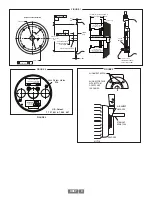


XR67 10
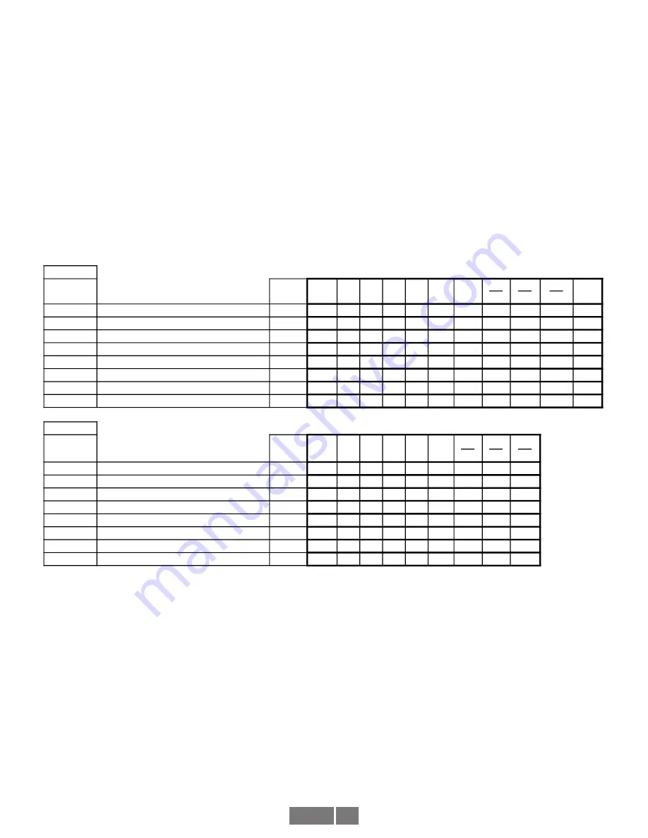
Connection
Description
Option
Code
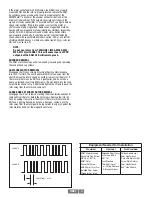
Phasing Signal
0V
Gnd A+
B+
Z+ Alm+ +Vin
A-
B-
Z-
Alm
Y
10 Pin MS Avtron / Northstar Pinout
CW
Pin #
A
D
E
C
NC
B
G
H
I
NC
A,C
10 Pin MS Small Encoder Std Pinout
CW
Pin #
F
A
B
C
NC
D
H
I
J
NC
B,D
10 Pin MS Small Encoder Dynapar Pinout
CCW
Pin #
F
A
B
C
NC
D
H
I
J
NC
R
10 Pin MS Mini Twist Lock
CW
Pin #
F
A
B
C
NC
D
H
J
K
NC
P
10 Pin, Mini Industrial, Avtron Pinout
CW
Pin #
1
2
3
4
5
6
7
8
9
10
G
10 Pin, Mini Industrial, Northstar Pinout
CW
Pin #
1
2
3
4
NC
6
7
8
9
NC
H,M,N,8
Conduit Box W/10 Pin Terminal Block
CW
Pin #
1
2
3
4
5
6
7
8
9
10
W
10 Conductor Wire Cable
CW
Color BLK GRN BLU ORG BRN RED
YEL
GRA
WHT VIO
Connection
Description
Option
Code
Phasing Signal
0V
Gnd A+
B+
Z+ +Vin
A-
B-
Z-
K
7 Pin MS, Avtron / BEI Pinout (A,A\,B,B\)
CW
Pin #
F
A
B
NC
D
C
E
NC
F
7 Pin MS, Avtron / BEI Pinout (A,A\)
CW
Pin #
F
A
NC
NC
D
C
NC
NC
J
7 Pin MS, Avtron / BEI Pinout (A,B,Z)
CW
Pin #
F
A
B
C
D
NC
NC
NC
E
7 Pin MS, Avtron / BEI Pinout (A,B)
CW
Pin #
F
A
B
NC
D
NC
NC
NC
V
7 Pin MS, Dynapar Pinout (A,A\,B,B\)
CCW
Pin #
F
A
B
NC
D
C
E
NC
T
7 Pin MS, Dynapar HS35 Pinout (A,A\)
CCW
Pin #
F
A
NC
NC
D
C
NC
NC
U
7 Pin MS, Dynapar HS35 Pinout (A,B,Z)
CCW
Pin #
F
A
B
C
D
NC
NC
NC
S
7 Pin MS, Dynapar HS35 Pinout (A,B)
CCW
Pin #
F
A
B
NC
D
NC
NC
NC
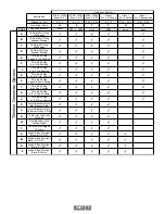
*
*
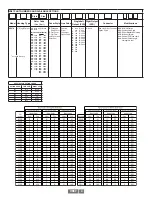
* Remote alarm function only connected for Zone 2, Zone 22 and Division 2
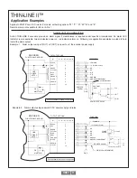
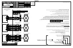
See the following Installation Drawings for Wiring Information
D52352: ATEX / IECEx Zone 1 & 21
D52353: ATEX / IECEx Zone 2 & 22
D52354: Division 1
D52355: Division 2
NOTE:
Remote alarm is not functional for Division 1, Zone 0 or Zone 1
Pinouts for Connector Options
Phasing is defined as the direction of rotation for which phase A leads B as viewed from the back of the Encoder
*
Remote alarm function not available with line driver options “H”, “5” or “F”
(Zone 0, Zone 1 or Class I Div I)
Summary of Contents for Avtron SMARTSafe XR67
Page 13: ...XR67 13...
Page 14: ...XR67 14...


