B R U S H L E S S D C M O T O R A N D G R E E N D R I V E
T M
M A N U A L
16
Nidec Motor Company
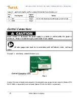
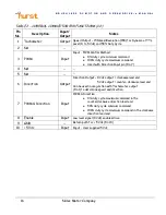
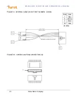
TABLE 2 - CONTROL CONNECTOR PIN FUNCTIONS (C2)
Pin
No.
Description
Input/
Output
Notes
1 Tachometer
Output
Speed Output – 15 Pulses/Revolution (PPR) for Dynamo at TTL
Level (0 to 5 Vdc) and 50% Duty Cycle
2 NA
--
--
3 PWM
Input
Input - PWM Control Method
●
0% duty cycle minimum command
●
100% duty cycle maximum command
●
Used with Direction Input pin (Pin 7)
4 NA
--
--
5 NA
--
--
6 Direction
Output
Direction Output – 0 Vdc output = clockwise lead end
5 Vdc output = counter-clockwise lead end
Can be used in conjunction with Tachometer output
(Pin 1) to determine speed and direction
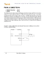
7 PWM
&
Direction
Input
PWM & Direction -
●
0% duty cycle maximum command in the
counterclockwise direction lead end
●
50% duty cycle minimum command
●
100% duty cycle maximum command in the clockwise
direction lead end
8 Enable
Input
Low level signal (0 Vdc) enables drive
9 GND
--
Return path for + 5 Vdc (Pin 10)
10 +5
Vdc
Input
Input - User supplied 5 Vdc

