7
■
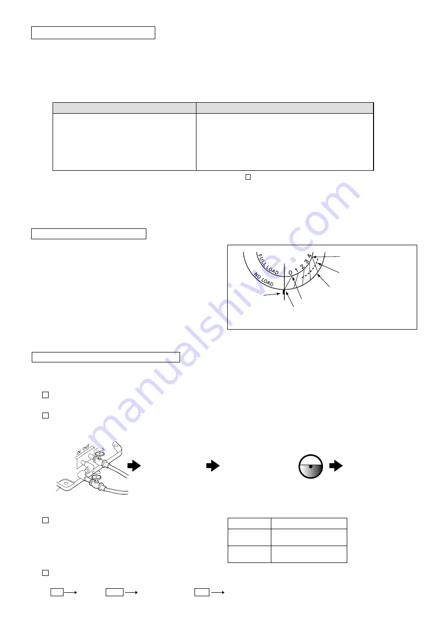
Operate the oil cooler pump unit according to the following procedures.
■ Be sure to provide a separate power supply to the pump unit from the speed drive motor.
1 Before operation, be sure to open the oil inlet (outlet) valves (two positions) of the speed drive.
* Operating the pump unit with those valves closed could result in malfunction of the pump unit.
2 Turn the power switch of the oil cooler pump unit ON, and confirm that there is no problem with oil feeding conditions between the speed drive
main unit and pump unit, then turn the power switch of the speed drive ON.
3 Confirm the rotation direction of the cooler pump unit motor.
1. Perform wiring so that the motor rotates in a counter-clockwise
direction when viewed from the motor fan side.
2. For the indication position of the rotation direction, refer to the table
on the right.
4 Inspection and cleaning of the oil filter
・ The filter clogging condition will be indicated by
“color”
in the detector inside the filter on top of the oil cooler pump unit, depending on the degree of use.
For NRXMK-18K (including models equipped with the reducer)
Blue
Yellow
White
Normal
Clean the element
Danger (clean or replace the element)
Model
Indication position
RXCA-01
RXCW-01
Indicated on the motor
RXCW-01-1
RXCW-01-2
Indicated on the pump unit
Turn the power switch of
the oil cooler pump unit ON
Open the oil inlet (outlet) valves of the speed drive
Turn the power switch
of the speed drive ON
Confirm that the oil cooler pump
unit has been filled with oil
Confirm that oil has been supplied at the specified
level of the oil gauge in the speed drive
Base
2-4 Operation of the oil cooler pump unit
1.
Never turn the speed change handle when operation stops
(when the motor is not running).
2. Be careful not to overload.
3.The surface temperature of the speed drive housing under normal operation can reach up to approximately 50ºC higher than
the ambient temperature.
4.If the following events occur, stop operation immediately, and inspect the unit. Take any necessary procedures.
* For more details on the above symptoms and possible causes of problems, refer to “ 5 Troubleshooting” on page 11.
5.Switch between forward and reverse rotation after checking that the motor (input) shaft has stopped operation completely.
Instantaneous switching between forward and reverse rotation could result in malfunction.
For NRX, the rotation will not change as long as the load
does not change.
If a load changes greatly, however, the rotation speed will
change even at the same graduation point.
1. Read the graduation on the dial depending on the load.
2. Note that the rotation speed will change if a load changes greatly.
(We recommend using the automatic control when high accuracy
is desired).
(*1) Rotation speed for the type without the reducer
2-2 Precautions during operation
2-3 Dial graduation and load
Symptoms
Possible causes
・ The temperature suddenly increases.
・ An abnormal, loud noise is suddenly generated.
・ The rotation speed suddenly becomes unstable.
・ Other abnormal events are found.
・ The unit has been overloaded
・ Lubricating oil has been excessively or insufficiently used,
or has deteriorated. Or, a different type of lubricating oil has
been used.
・ Bearings and/or drive surfaces have been damaged
・ Improper connecting conditions with the mated machine, etc.
Dial position at 100% load
Dail position at medium load
Mating mark
Dial position at no load
0 rpm at this point with 100% load
20 rpm (when 1800 rpm is input) at
this point with no load (*1)
Summary of Contents for RINDCODE NRX Series
Page 25: ......
Page 26: ......
Page 27: ......
Page 28: ...Address 1 Terada Kohtari Nagaokakyo city Kyoto 617 0833 Japan Phone 81 75 958 1298...


