background image

LLE14BRDA001A/E

 6 - 5

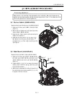
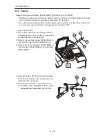
6.8 Cover Relay Board (44401-BA07)

Replacement part: Cover relay board (44401-BA07)
1. Remove the top cover ASSY. (44402-2100)

(see 5.4).

2. Disconnect all cables from the connector on

the cover relay board (44401-BA07).

3. Unscrew the P tight screws [40340-M047 (n =

4)] to replace the cover relay board.

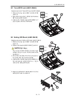
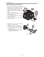
6.9  Sensor Cable (44401-CA37)

Replacement part: Sensor cable (44401-CA37)
1. Remove the top cover ASSY. (44402-2100)

(see 5.4).

2. Disconnect connector J3 (P703) from the

cover relay board (44401-BA07).

3. Unscrew the P tight screws [40340-M047 (n =

2)] to remove the sensor holder (44401-M222)
along with the sensor cable (44401-CA37).

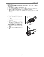
4. Unscrew CK2 × 8 (n = 2) to disconnect the

sensor cable (44401-CA37) from the sensor
holder (44401-M222). Replace the sensor
cable.

5. Reassemble the parts in the reverese order.

1) Perform the cover hardware test (see

Step 11 of 7.2.5).

4

 47

  BA07

 -21A0 

  44402

 -2100 

  44402

(200V)

(100V)

  CA37

2

CK2×8

222

2

 47

Summary of Contents for Le 1000

Page 1: ...PATTERNLESS EDGER Model SERVICE MANUAL June 2008 Pages in total 152 LLE14BRDA001A E...

Page 2: ...kyo Office Bunkyo Ku Tokyo 113 0033 Japan Telephone 81 3 5844 2641 Facsimile 81 3 5844 2642 NIDEKINCORPORATED 47651 Westinghouse Drive Fremont California 94539 U S A United States Agent Telephone 1 51...

Page 3: ...2 5 4 Removing Covers 5 2 6 REPLACEMENT PROCEDURES 6 1 6 1 Rocker Switch 80460 00123 6 1 6 2 Main Board 44401 BA01 6 1 6 3 Inverter 80607 00027 6 2 6 4 Monochrome LCD 80607 00025 6 2 6 5 Trace SW Boar...

Page 4: ...2 Pulse motor 44001 E037 Sensor cable 44001 CA17 6 23 6 36 Feedwater ASSY 44001 1600 6 24 6 37 Lid ASSY 44401 2200 6 24 6 38 DC Fan 40350 E016 6 25 6 39 Communication Connector Board 44401 BA08 6 25...

Page 5: ...7 26 7 4 1 Parameters BL motor inverter 7 26 7 4 2 Parameter list of BL motor 40340 E066 E067 inverter 7 27 7 4 3 Trip table of BL motor inverter 7 30 7 5 Calibration 7 31 7 5 1 Displaying calibration...

Page 6: ...ttings and Adjustments 7 57 7 7 1 Dressing wheels 7 57 8 SUPPLEMENT 8 1 8 1 Wiring Diagram 8 1 8 2 Connector Cable 8 2 8 3 Main Board 44401 BA01 8 7 8 4 Grease 8 8 8 5 Grease MSDS 8 10 8 5 1 NIPPECO L...

Page 7: ...nt Disassembly or repair must be performed by NIDEK service persons or other qualified personnel Refer to the Operator s Manual Parts List and Installation Manual for the Le 1000 Refer to the Service...

Page 8: ...This page is intentionally left blank LLE14BRDA001A E 1 2...

Page 9: ...n off the power switch disconnect the power cord from the outlet and investigate the cause If the system is powered in abnormal conditions fire electric shock or total loss of the system may result Se...

Page 10: ...This page is intentionally left blank LLE14BRDA001A E 2 2...

Page 11: ...and a blocker to check data transmission reception Visually check the volume of water Mechanical operation The processing chamber door and tracing unit lid are smoothly opened and closed Tactile chec...

Page 12: ...hing ability Width accuracy only the SFB unit equipped system Call up 45 internal data and flat edge a CR 39 lens with safety beveling The width is within the set value 40 or 0 2 mm whichever is large...

Page 13: ...the processing chamber Flow control Controls the flow volume of the cooling water poured over the wheels Display Shows lens shape and layout data Tracing unit lid The lid covers the tracing unit for m...

Page 14: ...ter RS 232C port COM2 Communication port for connection with an optional intelligence blocker Mode switch MODE Used to upgrade the software Contrast control CONTRAST VR Adjusts the contrast of the dis...

Page 15: ...ain Discharges the water curtain cooling water to keep the processing chamber clean Lens chuck Presses against a lens set in the cup holder to secure it Wheels Configured from multiple wheels see 3 4...

Page 16: ...tern or demo lens Rim clips Hold the rim of frames Pattern tracing pin Traces a pattern or demo lens to measure its shape Stylus Traces a frame groove to measure its frame shape button Starts left eye...

Page 17: ...ching button Switches safety beveling on or off button Secures a lens to or releases a lens from the lens chuck R L indicator lamp Lights up in green when the right eye lens is selected and in red whe...

Page 18: ...y the tracing unit on the display Lens button Used to select lens material among PLA plastic HPL high index plastic PC poly carbonate ACR acrylic resin TRX Trivex PUR polyurethane and GLS glass GLS ca...

Page 19: ...LLE14BRDA001A E 3 9 3 3 Model Configuration...

Page 20: ...LB 2R 40347 1050 PLB 2R Type Part No Roughing wheel for glass lenses Roughing wheel for plastic lenses Rotative direction Motor side Motor side Motor side Rotative direction Rotative direction Polishi...

Page 21: ...Stop Smooth stepless control Indicates that caution must be taken Refer to the operator s manual before use Indicates that the state of the power switch When the symbol side of the switch is pressed d...

Page 22: ...LLE14BRDA001A E 3 12 5 4 01 000000 9CVGT RTGUUWTG CZ M2C EU area only...

Page 23: ...out 2100 44402 1200 44001 1000 44402 1600 44001 1400 44401 1100 44001 4000 44401 4000 43401 4100 40340 9300 44401 9100 44001 6000 44001 5000 44401 12A0 44001 1A00 44402 100V 200V 100V 200V 5300 44001...

Page 24: ...LLE14BRDA001A E 3 14 3 7 Electrical Component Layout SYM PART NO DESCRIPTION BA07 CA26 BA02 BA03 E42 E54 E55 100V 200V E22 BA04 BA09 E87 E43 CA29 E66 E67 100V 200V E38...

Page 25: ...LLE14BRDA001A E 3 15 SYM PART NO DESCRIPTION E86 CA42 BA01 BA05 E37 CA17 E33 CA32 CA34 E35b E35a CA31 CA28 CA27 E84...

Page 26: ...LLE14BRDA001A E 3 16 SYM PART NO DESCRIPTION E79 2 CA07 E83 E82 E69 E43 BA08 E16 E85 E36 BA06 BA12 BA13 BA11 CA64 CA60 E39 CA63 CA61...

Page 27: ...LLE14BRDA001A 3 17 3 8 Replacement Part List Needs adjustment after replacement Needs confirmation after replacement...

Page 28: ...LLE14BRDA001A 3 18...

Page 29: ...EVGF RTQRGTN TGRNCEG KV H OCKP DQCTF KU EQPPGEVGF RTQRGTN TGRNCEG KV 2WUJ 56 46 59 YJKNG NKHV C 7 TTQT CRRGCTU GGNGTU CTG PQV KPKVKCNK GF CDNGU CPF CTG RQQTN EQPPGEVGF QT DTQMGP 2WNUG OQVQT KU RQQTN E...

Page 30: ...EWTTGPVU TTQT CRRGCTU 1XGTEWTTGPV QH 5 YJGGN OQVQT 5 CTO OQVQT 5 OQVQT QVQT QT FTKXG VTCPUOKUUKQP RCTVU UWEJ CU IGCTU JCXG UQOG VTQWDNG 5 QTKIKP UGPUQT KU FGHGEVKXG 5 ITQQXKPI 55 KU FGHGEVKXG JGEM OC...

Page 31: ...asssembly procedure However in exceptional cases the assembly procedure is specified 2 Each number in exploded diagrams indicates removal order or part number as shown to the right and numbers of remo...

Page 32: ...l 44401 M169 to lock it 5 4 Removing Covers 1 Turn off the power switch and unplug the power cord 2 Open the top cover ASSY 44402 2100 100 V or 44402 21A0 200 V and lock it see 5 3 3 Disconnect connec...

Page 33: ...left side cover 44401 M208 and right side cover 44401 M209 Open the top cover ASSY 44402 2100 100 V or 44402 21A0 200 V see 5 3 or remove it Then remove the left side cover 44401 M208 and right side c...

Page 34: ...LLE14BRDA001A E This page is intentionally left blank...

Page 35: ...nt part Main board 44401 BA01 1 Remove the top cover ASSY 44402 2100 left side cover 44401 M208 right side cover 44401 M209 and rear cover 44001 M203 see 5 4 2 Unscrew BS4 10 n 3 to remove the board h...

Page 36: ...nt part Monochrome LCD 80607 00025 1 Remove the top cover ASSY 44402 2100 see 5 4 2 Disconnect the LCD supplied cable from connector CN2 of the inverter 80607 00027 CAUTION High Voltage The inverter 8...

Page 37: ...Remove the top cover ASSY 44402 2100 see 5 4 2 Remove the inverter 80607 00027 see 6 3 CAUTION High Voltage The inverter 80607 00027 becomes high voltage Be sure to turn off the power while handling i...

Page 38: ...02 2100 see 5 4 2 Disconnect connector J1 P401 from the main SW board 44401 BA04 3 Unscrew the P tight screws 40340 M048 n 5 and spacers 44001 M275 n 5 to remove the main SW board 4 Remove 44001 M211...

Page 39: ...Sensor cable 44401 CA37 1 Remove the top cover ASSY 44402 2100 see 5 4 2 Disconnect connector J3 P703 from the cover relay board 44401 BA07 3 Unscrew the P tight screws 40340 M047 n 2 to remove the se...

Page 40: ...the long offset wrench toward the back of the system while holding the wheels by hand 4 Remove the hexagon bolt wheel retainer and wheel When using the wheel removal jig 40396 0100 Note Be careful not...

Page 41: ...eing 3 4 Wheel Configuration Make sure that the marked surface orientation and rotation direction are correct see 3 4 4 Loosely attach the hexagon bolt 40340 M722 and wheel retainer 40347 M721 by hand...

Page 42: ...he safety beveling grooving ASSY see 7 5 3 6 12 Stylus 40340 M474 Replacement part Stylus 40340 M474 1 Open the top cover ASSY 44402 2100 see 5 3 2 While the system is turned off turn the measuring pa...

Page 43: ...from the tracing unit board 40340 BA15 3 Loosen SB4 8 n 2 4 Unscrew SB4 8 n 2 to replace the tracing unit ASSY 43401 4000 5 Reassemble the parts in the reverse order 1 Write to the tracing unit CPU s...

Page 44: ...0 1 Open the lid ASSY 2 Lay a cloth inside the processing chamber beforehand so as not to lose the machine screws or feelers while handling 3 Remove the machine screws 40340 M994 n 4 from the feeler A...

Page 45: ...set screws 40340 M291 n 2 of the feeler ASSY 40340 4100 can be seen 3 Loosen the set screws 40340 M291 n 2 4 Remove the Allen screw 40340 M293 and 3PW4 to replace the feeler ASSY 40340 4100 5 Reassemb...

Page 46: ...assemble the parts in the reverse order The sleeve 40340 M995 of the lens measurement unit must be below the processing chamber door 1 Adjust the height of the feeler ASSY see 7 3 2 1 2 Adjust the fee...

Page 47: ...ove the encoder holder 40340 M288 along with the encoder 40340 E043 4 Unscrew CK2 5 n 2 to replace the encoder 40340 E043 5 Reassemble the parts in the reverse order Readjustment is necessary see 6 16...

Page 48: ...8 see 5 4 2 Remove the hose clip 44001 M070 and duct 40350 M084 see 5 4 3 Disconnect connector J1 P601 from the board 40340 BA06 4 Peel off the protective sheet 44001 M905 5 Disconnect connector CN03...

Page 49: ...ing ASSY 44001 6000 see 6 21 2 Unscrew SB3 6 n 4 to remove the motor support 44001 M661 along with the pulse motor 40340 E035 3 Loosen HH3 4 n 2 and unscrew FC3 8 n 4 to replace the pulse motor 40340...

Page 50: ...ectors CN01 and CN02 of the brushless motor 5 Remove the collar 40347 M717 and spacer 40347 M718 by hand 6 Unscrew SB6 20 n 4 to remove the motor ASSY 44401 1400 7 Unscrew SB4 12 n 4 to replace the br...

Page 51: ...the guide 44001 M931 6 27 Processing Chamber ASSY 44401 9300 Replacement part Processing chamber ASSY 44401 9300 1 Remove the top cover ASSY 44402 2100 left side cover 44401 M208 and right side cover...

Page 52: ...ight side cover 44401 M209 see 5 4 2 Remove the guide 44401 M931 see 6 27 3 Remove the feeler ASSY 40340 4100 see 6 15 4 Remove the safety beveling grooving ASSY 44001 6000 see 6 21 5 Remove the motor...

Page 53: ...1 Adjust the carriage ASSY see 7 3 1 2 Perform the arm position adjustment and calibration of the safety beveling grooving ASSY 44001 6000 see 7 3 3 1 and 7 5 3 3 Adjust the height of the feeler ASSY...

Page 54: ...nector J5 P505 of the carriage relay board 44401 BA05 3 Unscrew SB6 10 to replace the Y axis motor ASSY 44001 5400 4 Reassemble the parts in the reverse order 1 Adjust the carriage ASSY see 7 3 1 2 Pe...

Page 55: ...e parts in the reverse order Adjust the chuck pressure see 7 3 4 6 32 q Axis Stepping Motor 44401 E022 Replacement part axis stepping motor 44401 E022 1 Remove the top cover ASSY 44402 2100 left side...

Page 56: ...cover 44401 M208 and right side cover 44401 M209 see 5 4 2 Disconnect connectors J4 P504 and J6 P506 of the carriage relay board 44001 BA05 3 Unscrew CK2 4 n 2 for each to replace the sensor cables 4...

Page 57: ...o replace the X axis motor ASSY 44001 1100 4 Reassemble the parts in the reverse order 1 Adjust the engagement of the motor gear in the X axis motor ASSY see 7 3 1 2 6 35 2 Pulse motor 44001 E037 Sens...

Page 58: ...001 M165 6 Unscrew AS4 10 n 2 to replace the feedwater ASSY 44001 1600 7 Reassemble the parts in the reverse order 1 Apply the gasket material 1211 to the joint 44001 M866 2 Insert the tube 44001 M080...

Page 59: ...401 BA08 1 Remove the top cover ASSY 44402 2100 and rear cover 44001 M203 see 5 4 2 Remove the tracing unit ASSY 43401 4000 see 6 13 3 Disconnect all connectors from the communication connector board...

Page 60: ...the reverse order Attach the fuse holder so that P on the fuse holder terminal appears as shown to the right 6 42 Inlet 80457 00085 Replacement part Inlet 80457 00085 1 Remove the top cover ASSY 44402...

Page 61: ...4 Unscrew SPC4 6 n 2 to replace the reactor 40350 E043 6 44 Regenerative Resistor for BL Motor 40340 E069 Replacement part Regenerative resistor for BL motor 40340 E069 1 Remove the top cover ASSY 44...

Page 62: ...or 40340 E066 E067 Replacement part Inverter for BL motor 40340 E066 for 100 V or 40347 E067 for 200 V 1 Remove the top cover ASSY 44402 2100 rear cover 44001 M203 left side cover 44401 M208 and right...

Page 63: ...ar cover 44001 M203 left side cover 44401 M208 and right side cover 44401 M209 see 5 4 2 Remove the mains part ASSY 44401 1200 for 100 V or 44401 12A0 for 200 V see 6 47 3 Disconnect all connectors fr...

Page 64: ...t side cover 44401 M208 and right side cover 44401 M209 see 5 4 2 Remove the mains part ASSY 44401 1200 for 100 V or 44401 12A0 for 200 V see 6 47 3 Remove all terminals from the line noise filter 804...

Page 65: ...al adjustment of the SFB arm height and adjustment of the lens measuring feeler height as they become the standards for adjustments If they are not fully adjusted accuracy in grooving and safety bevel...

Page 66: ...e 1000 Nothing appears on the display and initialization does not start When the protection switch is not released the normal operation starts 6 Double clic the file to be downloaded ex LE14A_Master_V...

Page 67: ...while pressing to display the SYSTEM SETTING MODE screen 3 Press to align the arrow to EEPROM INITIALIZE then press The EEPROM INITIALIZE screen appears 4 Press to align the arrow to INITIALIZE and pr...

Page 68: ...ased in Step 4 the tracing unit starts the normal operation 6 Activate Flash Writer PRO 7 Click Setting and set the following items as shown to the right 1 Select CPU 2 CPU operation clock 3 COM Port...

Page 69: ...ing The SYSTEM SETTING MODE screen appears 3 Press to move the arrow to PARAMETER SETTING then press The PARAMETER SETTING screen appears 4 Press or to move the arrow to each item 5 Press or to change...

Page 70: ...M SETTING MODE screen appears 3 Press to move the arrow to WHEEL PARAMETER then press The WHEEL PARAMETER screen appears 4 Press or to move the arrow to the desired item 5 P ress or to change paramete...

Page 71: ...in OFF OFF ON Master Size 0 00 9 99 9 99 Cover Sensor Mes OFF Mes Stop Both Baud Rate for TRACER 38400 9600 38400 Baud Rate for EXT 9600 9600 38400 Communication Device FA 10 SI 30 FA 10 Blocker Suppo...

Page 72: ...size HPL bevel 0 00 9 99 9 99 Polish size HPL flat 0 00 9 99 9 99 POL Differential PC 0 20 9 99 9 99 Polish level PLA flat 0 30 9 99 9 99 Polish level PC flat 0 30 9 99 9 99 Polish level PLA bvl 0 20...

Page 73: ...reset PLA CEL 0 00 9 95 9 95 Size preset GLS MTL 0 00 9 95 9 95 Size preset GLS CEL 0 00 9 95 9 95 Initial value of FPD 70 0 99 5 30 0 Initial value of PD 62 0 99 5 30 0 Layout preset 2 0 15 0 15 0 Me...

Page 74: ...and OFF ON OFF is adjusted with and 6 Y Axis 1 Displays the Y axis origin sensor between ON and OFF ON OFF is adjusted with and Note The Y axis does not move even when or is pressed while Power is se...

Page 75: ...ing Open opens the chuck axis 3 Pressing Close closes the chuck axis 9 SFB 1 Displays the SFB ASSY origin sensor between ON and OFF 2 Pressing Init sets the SFB ASSY in the standby position Pressing D...

Page 76: ...s around 740 When it is in the measurement position DOWN the lift value is around 140 11 COVER 1 Displays the lid ASSY open close sensor between ON and OFF 2 Opening the lid ASSY by hand displays OPEN...

Page 77: ...ight so that the bearing 40340 M556 can be seen properly 3 Loosen SB5 25 fixing the bush 40340 M571 of the carriage ASSY 4 Turn the bush 40340 M571 of the carriage ASSY with a pair of long nose pliers...

Page 78: ...68 of the carriage ASSY 3 Loosen SB4 10 n 2 on the rack Move the X axis motor ASSY to the rack side and fix the ASSY 4 While pressing the rack against the motor gear retighten SB4 10 n 2 on the rack 5...

Page 79: ...ON screen to set the carriage ASSY X axis free see 7 5 1 2 Open the top cover ASSY 44402 2100 see 5 3 3 Remove the wheels see 6 10 4 Attach the Y axis adjustment jig 40396 M002 through the shaft of th...

Page 80: ...en to set the carriage ASSY X axis free see 7 5 1 2 Loosen HH6 6 n 2 of the large pulley 44001 M583 see the lower right figure Turn the left shaft to align its pin 44001 M551 to the notch of the Y axi...

Page 81: ...xis see 7 3 1 4 remove the Y axis adjustment jig 40396 M002 3 Attach the left right shaft adjustment jig 40396 M001 to the left shaft 4 Turn the timing belt by hand to move the right shaft close to th...

Page 82: ...isplay the SYSTEM SETTING MODE screen Press DATA on the CALIBRATION screen to set the carriage X axis free see 7 5 1 7 Lower the feeler ASSY by turning manually the arrow indicating area of the lens m...

Page 83: ...lens measurement unit ASSY see 7 5 5 2 Adjust the feeler axis see 7 6 1 7 3 2 3 Voltage of lens measurement unit ASSY Purpose Adjusting the initial position of the feeler ASSY 40340 4100 1 Open the to...

Page 84: ...SB4 10 n 2 fixing the cover support 40340 M290 With the cover ASSY closed press the cover support against the cover ASSY and retighten SB4 10 n 2 to fix the cover support 8 Reassemble the parts in the...

Page 85: ...ght figure indicated by the arrow Loosen the set screws SB4 6 n 2 of the spindle ASSY 6 Loosely attach the SFB adjustment jig 40396 M003 to the shaft of the motor ASSY 40347 1400 by turning manually t...

Page 86: ...ove the shading plate 44001 M554 of the chuck pressure sensor 44001 CA27 to the left by increasing the pressure or to the right by decreasing the pressure 4 Display an appropriate job or internal data...

Page 87: ...ob or internal data to enter the desired layout 5 Set the chuck pressure measurement jig 40391 0100 and press and 6 Pressing fully tightens the chuck so press to suspend the processing and check the c...

Page 88: ...s toward the frame and that the angle where the stylus contacts the frame is 90 4 If the angle is not 90 follow Steps 2 and 3 in 6 12 Stylus to adjust the angle replacement of stylus is not necessary...

Page 89: ...solution 1 Turn on the power 2 Open fully the sliders of the tracing unit hold them by hand and press 3 When the pattern tracing pin comes out and tracing starts turn off the power 4 Soak the lint fr...

Page 90: ...s or to select the desired parameter No For parameter No 100 or later blinks to the lower right of the two digit LED display The trip history is saved in parameters No 81 through 85 The latest trip hi...

Page 91: ...LLE14BRDA001A E 7 27 7 4 2 Parameter list of BL motor 40340 E066 E067 inverter User parameter...

Page 92: ...LLE14BRDA001A E 7 28 User parameter...

Page 93: ...LLE14BRDA001A E 7 29 System parameter...

Page 94: ...o each inverter during slowdown it will be tripped 0 C C If the detected value exceeds the current set to each inverter it will be tripped 0 U Regeneration overvoltage protection When the direct volta...

Page 95: ...ON then press The CALIBRATION screen appears 7 5 2 Attaching calibration jig Purpose Attaching the calibration jig 40396 M011 Jig Calibration jig LEDJ 16 40396 M011 1 Remove the cup holder with a hexa...

Page 96: ...sition of the arm in the safety beveling grooving ASSY see 7 3 3 1 2 Display the SYSTEM SETTING MODE screen CALIBRATION screen see 7 5 1 3 Attach the calibration jig 40396 M011 see 7 5 2 4 Pressing di...

Page 97: ...tion approx 2 minutes Jig Calibration jig LEDJ 16 40396 M011 1 Display the SYSTEM SETTING MODE screen CALIBRATION screen see 7 5 1 2 Attach the calibration jig 40396 M011 see 7 5 2 3 Pressing starts W...

Page 98: ...SY 44401 4000 approx 1 minute Jig Calibration jig LEDJ 16 40396 M011 1 Display the SYSTEM SETTING MODE screen CALIBRATION screen see 7 5 1 2 Attach the calibration jig 40396 M011 see 7 5 2 3 Pressing...

Page 99: ...ng frame calibration of the tracing unit using the 45 standard frame jig Jig 45 standard frame jig LEDJ 10 40390 M301 1 Set the 45 standard frame jig 40390 M301 2 Press 4 while pressing 3 After confir...

Page 100: ...standard frame jig LEDJ 10 40390 M301 30 standard frame jig LEDJ 10 40390 3100 60 standard frame jig LEDJ 10 40390 3300 1 Set the 45 standard frame jig 40390 M301 to the left end of the sliders as sho...

Page 101: ...g 40390 M301 in the center of the sliders as shown to the right 11 Press 12 After measurement is completed confirm that the LEDs of 4 and alternately blink Then set the 45 standard pattern jig 41476 M...

Page 102: ...Press while pressing to display the SYSTEM SETTING MODE screen 3 Press to move the arrow to PARAMETER SETTING Then press to display the PARAMETER SETTING screen 4 Press to move the arrow to Measure Ax...

Page 103: ...ally right up increase the value when the trace is diagonally down decrease the value to perform axis adjustment 2 Adjust the front feeler axis as follows 1 Prepare a flat lens and apply powder or gre...

Page 104: ...t trace is diagonally right up increase the value when the trace is diagonally right down decrease the value to perform axis adjustment 7 Apply powder or grease to the front surface of the same lens 8...

Page 105: ...ocessed lens Press or to change the parameter value so that the diameter is 45 00 0 05 mm for beveling and 45 00 0 10 mm for flat edging 6 When the diameter of the processed lens is 46 00 mm input 1 0...

Page 106: ...e moves the bevel position toward the front surface Increasing the value moves the bevel position toward the rear surface 6 Adjust the bevel position of a glass lens in the same manner 7 6 4 Lens axis...

Page 107: ...ly right up increase the value If the lens top edge is diagonally right down decrease the value When drawing a horizontal line on a lens 1 Call up the 45 internal data 2 Process a lens blocked while a...

Page 108: ...ent and press The Size adjustment screen appears 3 Press to move the arrow to Polish level PLA flat Press or to set the value to 0 00 4 Call up the 45 internal data and set as follows SIZ 9 00 Polish...

Page 109: ...n on the main body and press to display the MENU screen 2 Press to move the arrow to Size adjustment and press The Size adjustment screen appears 3 Press to move the arrow to Polish level PLA bevel Pr...

Page 110: ...o Polish bevel const Press or to adjust the numeric value Increasing the value moves the bevel position to be polished to the lens front side Decreasing the value moves the bevel position to be polish...

Page 111: ...hange the GLS AXIS const flat parameter value Perform adjustment so that each edge of 45 is polished evenly from left to right 1 Press to display the MENU screen 2 Press to move the arrow to AXIS adju...

Page 112: ...change the GLS AXIS const bevel parameter value Perform adjustment so that each edge of 45 is polished evenly from left to right 1 Press to display the MENU screen 2 Press to move the arrow to AXIS ad...

Page 113: ...shing and the lens edge is well polished 7 6 5 6 Polish size Purpose Adjusting polish size of a lens processed with the 45 internal data Jig For adjusting CR39 polish size a lens of 3 to 5 D is recomm...

Page 114: ...rrow to Groove SFB adjustment and press The Grrove SFB adjustment screen appears 3 Call up the 45 internal data 4 Select NYL nylor and GUI guided and set the depth to 0 0 Groove a CR39 3 to 5 D lens 5...

Page 115: ...he arrow to Groove SFB adjustment and press The Grrove SFB adjustment screen appears 3 Call up the 45 internal data 4 Select NYL and GUI curve 5 5 and set the position to 0 0 Groove a CR39 3 to 5 D le...

Page 116: ...the arrow to AXIS adjustment and press The AXIS adjustment screen appears 3 Call up the 45 internal data 4 Select NYL and GUI and set the depth to 0 0 Groove a CR39 3 to 5 D lens 5 Confirm that the g...

Page 117: ...justment screen appears 3 Set each value of the SFB Width parameters enclosed by the dotted line in the figure as shown to the right to 0 3 mm Beveling safety beveling wheel position adjustment 1 Call...

Page 118: ...crease the values 7 6 8 Bevel safety bevel axis Purpose Adjusting beveling safety beveling axis for a lens processed with the 45 internal data Jig A CR39 3 to 5 D lens 1 Turn on the main body and pres...

Page 119: ...to move the arrow to SFB AXS const BVL R then press or to change the parameter value When the safety bevel width on the right side of the top edge is wider increase the value When the safety bevel wi...

Page 120: ...he right side of the top edge is wider decrease the value When the safety bevel width on the left side of the top edge is wider increase the value 6 Check the safety bevel axis on the rear surface Con...

Page 121: ...o may damage the wheel which prevents normal lens processing 3 Apply only the flat surface of the tip of the dressing stick to the wheel not its corners Otherwise the wheel may be damaged 4 Hold the d...

Page 122: ...the stick to the wheel for approx 5 seconds 5 Release the dressing stick from the wheel 6 Press Start the cooling water to wash the wheel surface away 7 Repeat Steps 3 to 6 two or three times 8 Press...

Page 123: ...y cloth Do not scrub the wheel roughly with the cloth Cloth fibers may remain interfering with polishing 11 When the surface of the polishing wheel dries confirm that the compound is completely washed...

Page 124: ...htly touch the dressing stick to the grooving wheel from directly above until the dressing stick is slightly grooved 5 Dress the wheel by slightly moving the dressing stick to left and right 6 Release...

Page 125: ...8 1 LLE14BRDA001A E 8 1 Wiring Diagram 5 6 0 59 80602 00107 80404 00043 80457 00085 80401 00038 80460 00123 8 SUPPLEMENT...

Page 126: ...LLE14BRDA001A E 8 2 8 2 Connector Cable...

Page 127: ...LLE14BRDA001A E 8 3...

Page 128: ...LLE14BRDA001A E 8 4...

Page 129: ...LLE14BRDA001A E 8 5...

Page 130: ...LLE14BRDA001A E 8 6...

Page 131: ...LLE14BRDA001A E 8 7 44401 BA01 2 2 2 2 2 2 2 2 2 2 2 44401 BA01 MAIN BOARD 2 2 2...

Page 132: ...616 623 633 574 629 642 637 636 CA34 291 2 660 619 618 687 690 610 609 692 606 663 686 693 685 689 611 2 612 815 Grease NBU15 E55 718 E54 717 100V 200V E55 E54 Grease NBU15 Grease NBU15 44401 1400 10...

Page 133: ...7 548 545 541 553 68 502 504 2 4 2 505 528 561 527b 2 522b 511 2 521 527c 501 586 522a 500 20 558 545 541 502 506 509 502 514 510 515 517 518 2 2 551 551 527a 66 587 589 82011 2537C 82011 1532C 82011...

Page 134: ...LLE14BRDA001A E 8 10 8 5 Grease MSDS 8 5 1 NIPPECO LLP...

Page 135: ...LLE14BRDA001A E 8 11...

Page 136: ...GPFGF YV QRVKQPCN FKVGTVKCT DWV N OGVJ N RJGPQN 5 0Q 69 OI O 69 OI O CKP KPITGFKGPVU 4GHKPGF OKPGTCN CPF 5 PVJGVKE J FTQECTDQP DCUG QKN 0QV FGUKIPCVGF 0QV FGUKIPCVGF KVKWO UQCR VJKEMGPGT 0QV FGUKIPCVG...

Page 137: ...CR CPF YCVGT GU EQPVCEV NCUJ VJQTQWIJN YKVJ YCVGT CNN C RJ UKEKCP PIGUVKQP QPUCNV C RJ UKEKCP 5GEVKQP 2TGECWVKQPU HQT 5CHG CPFNKPI CPF 7UG 5VGRU VQ G 6CMGP KP CUG CVGTKCN KU 4GNGCUGF QT 5RKNNGF 5ETCRG...

Page 138: ...CTFQWU QORQPGPVU 5RGEKHKE JGOKECN FGPVKV QOOQP 0COG U 15 2 6 8 4GEQOOGPFGF QRVKQPCN CKP KPITGFKGPVU 5 PVJGVKE J FTQECTDQP DCUG QKN 0QV FGUKIPCVGF 0QV FGUKIPCVGF KVJKWOW UQCR VJKEMGPGT 0QV FGUKIPCVGF 0...

Page 139: ...F YCVGT GU EQPVCEV NCUJ VJQTQWIJN YKVJ YCVGT CNN C RJ UKEKCP PIGUVKQP QPUCNV C RJ UKEKCP 5GEVKQP 2TGECWVKQPU HQT 5CHG CPFNKPI CPF 7UG 5VGRU VQ G 6CMGP KP CUG CVGTKCN KU 4GNGCUGF QT 5RKNNGF 5ETCRG WR Y...

Page 140: ...LLE14BRDA001A E 8 16 8 5 4 NBU15...

Page 141: ...LLE14BRDA001A E 8 17...

Page 142: ...LLE14BRDA001A E 8 18...

Page 143: ...LLE14BRDA001A E 8 19...

Page 144: ...LLE14BRDA001A E 8 20...

Page 145: ...LLE14BRDA001A E 8 21 8 6 Troubles and Measures...

Page 146: ...LLE14BRDA001A E 8 22...

Page 147: ...LLE14BRDA001A E 8 23...

Page 148: ...LLE14BRDA001A E 8 24...

Page 149: ...LLE14BRDA001A E 8 25...

Page 150: ...0 standard frame 40390 3300 Wheel remover 40396 0100 30 standard frame 40390 3100 Long offset wrench 40390 M603 Left right shaft rotation adjustment jig 40396 M001 Y axis adjustment jig 40396 M002 SFB...

Page 151: ...per 45 125 T 7 Settsu Kinzoku Kogyo Hand lap C type 47 185 01 Iuchi Seieido Soldering iron 20 30 W N453P Hakko Cleaner for soldering iron tip H 8 Hozan Multimeter MD 180C Sanwa Denki Keiki Vernier cal...

Page 152: ...LLE14BRDA001A E 8 28 This page is intentionally left blank...

Reviews: