LLE14BRDA001A/E
6 - 25
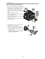
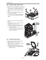
6.38 DC Fan (40350-E016)
Replacement part: DC fan (40350-E016)
1. Remove the top coverASSY. (44402-2100)
and rear cover (44001-M203) (see 5.4).
2. Disconnect connector CN08 of the DC fan
(40350-E016).
3. Unscrew PC4 × 30 (n = 4) to remove the DC
fan (40350-E016).
4. Reassemble the parts in the reverse order.
* Attach the DC fan so that the hole for the
cable is oriented as shown to the right.
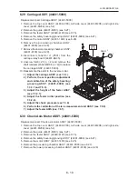
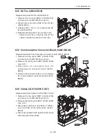
6.39 Communication Connector Board (44401-BA08)
Replacement part: Communication connector board (44401-BA08)
1. Remove the top cover ASSY. (44402-2100)
and rear cover (44001-M203) (see 5.4).
2. Remove the tracing unit ASSY. (43401-4000)
(see 6.13).
3 . D i s c o n n e c t a l l c o n n e c t o r s f r o m t h e
communication connector board (44401-
BA08).
4. Remove the connector locks (n = 4) to replace
the communication connector board (44401-
BA08).
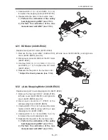
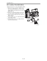
6.40 Cables CA07 (44001-CA07)
Replacement part: Cables CA07 (44001-CA07)
1. Remove the top cover ASSY. (44402-2100)
and rear cover (44001-M203) (see 5.4).
2. Remove the tracing unit ASSY. (43401-4000)
(see 6.13).
3. Disconnect connectors J6 (P906), J7 (P907),
and J8 (P908) of the SSR board (44001-
BA09).
4. Disconnect cables CA07 (44001-CA07) while
pressing each three clasps.
E16
4
PC4×30
BA08
80453-
03279
4
CA07
3
Summary of Contents for Le 1000
Page 1: ...PATTERNLESS EDGER Model SERVICE MANUAL June 2008 Pages in total 152 LLE14BRDA001A E...
Page 8: ...This page is intentionally left blank LLE14BRDA001A E 1 2...
Page 10: ...This page is intentionally left blank LLE14BRDA001A E 2 2...
Page 19: ...LLE14BRDA001A E 3 9 3 3 Model Configuration...
Page 22: ...LLE14BRDA001A E 3 12 5 4 01 000000 9CVGT RTGUUWTG CZ M2C EU area only...
Page 28: ...LLE14BRDA001A 3 18...
Page 34: ...LLE14BRDA001A E This page is intentionally left blank...
Page 91: ...LLE14BRDA001A E 7 27 7 4 2 Parameter list of BL motor 40340 E066 E067 inverter User parameter...
Page 92: ...LLE14BRDA001A E 7 28 User parameter...
Page 93: ...LLE14BRDA001A E 7 29 System parameter...
Page 126: ...LLE14BRDA001A E 8 2 8 2 Connector Cable...
Page 127: ...LLE14BRDA001A E 8 3...
Page 128: ...LLE14BRDA001A E 8 4...
Page 129: ...LLE14BRDA001A E 8 5...
Page 130: ...LLE14BRDA001A E 8 6...
Page 131: ...LLE14BRDA001A E 8 7 44401 BA01 2 2 2 2 2 2 2 2 2 2 2 44401 BA01 MAIN BOARD 2 2 2...
Page 134: ...LLE14BRDA001A E 8 10 8 5 Grease MSDS 8 5 1 NIPPECO LLP...
Page 135: ...LLE14BRDA001A E 8 11...
Page 140: ...LLE14BRDA001A E 8 16 8 5 4 NBU15...
Page 141: ...LLE14BRDA001A E 8 17...
Page 142: ...LLE14BRDA001A E 8 18...
Page 143: ...LLE14BRDA001A E 8 19...
Page 144: ...LLE14BRDA001A E 8 20...
Page 145: ...LLE14BRDA001A E 8 21 8 6 Troubles and Measures...
Page 146: ...LLE14BRDA001A E 8 22...
Page 147: ...LLE14BRDA001A E 8 23...
Page 148: ...LLE14BRDA001A E 8 24...
Page 149: ...LLE14BRDA001A E 8 25...
Page 152: ...LLE14BRDA001A E 8 28 This page is intentionally left blank...


