3-6 AC+DC Watt Measurement
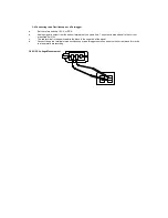
a. Set the rotary switch at KW/600V or KW/250V.
b. Insert the test leads into the input jack.
c. Connect the test probes of the test leads to the circuit to be measured (COM to ground, V to active line).
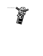
d. Clamp on to the active line
e. The watt clamp meter will automatically select proper range. If users want to select range, press the range button.
f .Read the measured value from the LCD display.
3-7 Temp
e
rature Measurement
Turn the switch to the temperature position. Connect the adapter (optional) to the V terminal. Then plug in the K type
thermal couple to the adapter. LCD will display the temperature measured
3-8
Continuity Measurement
a. Set the rotary switch at Continuity
b. Insert the test leads into the input jack.
c. Connect the test prods of the test leads to the two ends of the resistor or circuit to be measured.
d. Read the measured value from the LCD display.
e. If the resistance is lower than 40
Ω
, a beeping sound will be heard
Summary of Contents for NI349PR
Page 1: ...AC DC POWER CLAMP MULTIMETER NI349PR Manual...
Page 7: ...Figure 1...
Page 18: ...3 2 AC Current Measurement...
Page 20: ...3 3 DC Current Measurement...

