15
F. CONVEYOR BELT TENSION
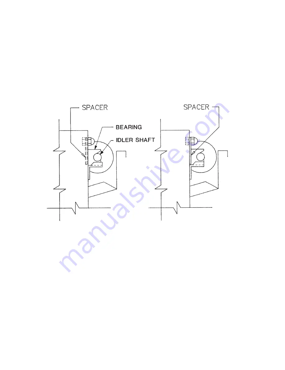
Maintain proper tension on the conveyor belts to prevent jamming. Bearing spacers (pictured below) are
supplied with the broiler to make minor tension adjustments. Major tension adjustments are made by
removing a link or links from the belt.
The diagram on the left shows the spacer in the stored position. The diagram on the right shows the
spacer behind the teflon bearing tightening the belts.
Belt tension should be checked monthly. To do this, allow the machine to cool, then grip the idler shaft at
each end and pull on it. If the shaft and bearings move 3/16” or more, the spacers should be placed
behind the bearings to tighten the belts. If the spacers are already behind the bearings, return them to
the stored position and remove a link from the conveyor belt.
BROIL BELT PROBLEMS
Interference with stripper blade:
The most common belt problem to be expected is the physical interference of the belt with the stripper
blade. This is caused by bent or warped rods on the meat belt, and can be fixed by replacing the rods
that are causing the problem. Other causes are bent stripper blades, or utensils jammed in the belt.
Blocked belts:
When trouble shooting drive problems, it is important to ensure that the belt is not being blocked. To do
this, detach the drive chain and turn the meat belt by hand. The belt, with the motor detached, should
turn freely and easily. If the blockage has occurred which is preventing the belt from turning, the block-
age should be removed before the drive chain is re-attached. The drive chain can be easily removed
from the drive sprocket (on the motor shaft) by loosening the mounting bolts and raising the motor.
Summary of Contents for 930 GAS
Page 2: ......
Page 16: ...16 G PARTS AND LOCATION Model 980 Gas Feed End View ...
Page 17: ...17 G PARTS AND LOCATION Model 980 Gas Left Side View ...
Page 18: ...18 G PARTS AND LOCATION Model 980 Gas Right Side View ...
Page 19: ...19 G PARTS AND LOCATION Model 950 Gas Feed End View ...
Page 20: ...20 G PARTS AND LOCATION Model 950 Gas Left Side View ...
Page 21: ...21 G PARTS AND LOCATION Model 950 Gas Right Side View ...
Page 22: ...22 G PARTS AND LOCATION Model 930 Gas Feed End View ...
Page 23: ...23 G PARTS AND LOCATION Model 930 Gas Left Side View ...
Page 24: ...24 G PARTS AND LOCATION Model 930 Gas Right Side View ...
Page 30: ...30 J WIRING DIAGRAM 930 950 980 Gas Domestic U S A ...


