5.06 Power Connections
The power tail from NightRunners balun is terminated with a
2.1mm DC Barrel plug, with a positive center pin. Connect your
DC supply to this plug using the Screw Terminal DC Socket
supplied. Always ensure your power supply is protected by a
sufficiently rated fuse or breaker. The NightRunner balun is fitted
with a 3A resettable fuse for added safety.
To prolong the lifespan of the thermal cameras sensor, it is
recommended that power to the camera is routed via a helm
mounted switch, and that the camera is switched off when
not in use.
The table below provides information on current draw depending
on the input voltage:
Input
Voltage
Consumption
(Idle)
Consumption
(Full Load)
At Cable
Distance
12VDC
1.2A
2.2A
60ft
24VDC
500mA
650mA
60ft
Details on the considerations that apply if you need to extend
the 60ft CAT5 cable supplied are listed in the section below.
5.07 Extending Cable Length
In the event that the 60ft cable supplied is not long enough, the
following considerations must be taken into account. Failure to
do so could result in damage to the camera, vessel and possibly
personal injury. Electrical connections to NightRunner must only
be conducted by fully qualified personnel.
1. On no account must a CAT5 cable longer than the 60ft cable
supplied be used to deliver power to the camera. Take power
locally to the end of the 20m cable or run a separate power
cable, suitably rated, back to the supply. Iris supply a
combined CAT5 + 2 core cable for this very purpose.
2. Video and Data can be extended further using CAT5 cable
and an additional set of baluns. Part numbers for cable
extension accessories are as follows:
Part No
Item
IRIS295-EXT-XX
Extension Kit. XX denotes cable length
CAT5-2-XX
CAT5 Cable + 2 Cores for Extending
DC Supply.
ʻ
XX
ʼ
denotes desired
length in meters.
BAL295
NightRunner Balun (Individual)
IM-POW-XX
DC Power Cable (50V, 5A).
ʻ
XX
ʼ
denotes desired length in meters
IM-BNC-XX
75
Ω
RG59 Coaxial Cable (BNC~BNC)
Video Extension Cable.
IM-DAT-XX
Single Twisted Pair Data Cable for
RS485 Control.
ʻ
XX
ʼ
denotes desired
length in meters.
Part No
Item
BNC-THRU
Straight Thru BNC Adapter
3. The diagram in section 6.03 illustrates methods of
extending the cabling.
5.08 Setting Camera Address / Image FLIP
Each camera must have it
ʼ
s own unique address so that only
control data intended for that camera is received and processed
by the camera. If multiple cameras had the same address, they
would all move together when pan and tilt commands are
transmitted.
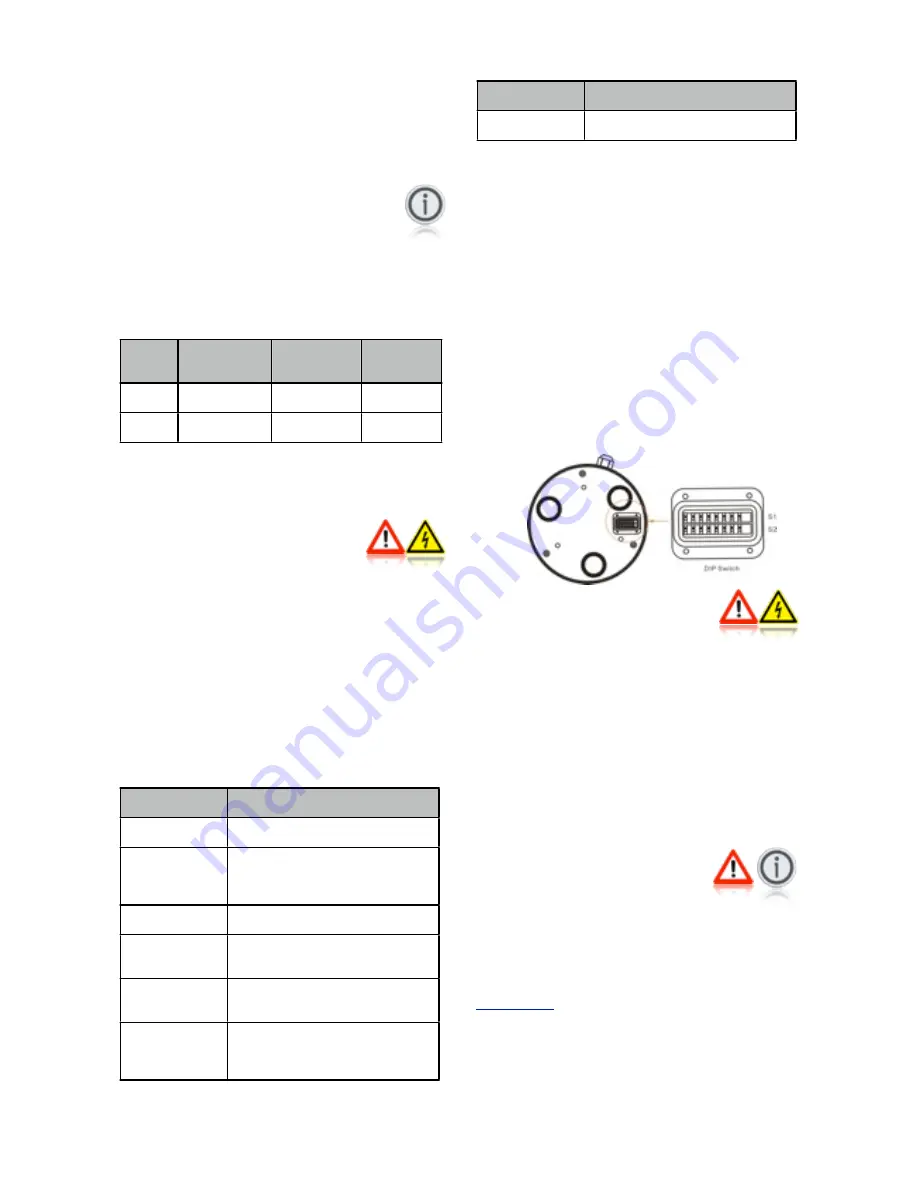
To set the camera address, remove the DIP switch cover plate
on the base of the camera with a small cross-head screw driver,
taking care not to loose the 4 screws or the rubber
ʻ
O
ʼ
seal, and
set the DIP switches on switch bank 1 accordingly. A table
detailing the switch settings can be found at the end of this
document and further details in Appendix A (Page 19)
Once the desired address has been set, carefully replace the
DIP switch cover plate.
Switch No.8 on bank S1 will also set the image orientation. See
section 10.02 Hardware Image Flip for details.
5.09 Installation Considerations
It's important to fully consider the intended position of the
camera and the desired fields of view prior to installation, in
terms of how you are going to get cables to the position, will the
camera be able to see the appropriate areas, will the camera
interfere with any other fixture such as a doorway or walkway
once it's fixed in place, or are there any obstructions behind the
surface onto which the camera is to be installed. It's strongly
recommended that if possible the camera should be temporarily
powered up prior to final installation and offered into position so
that these factors can be considered and any possible issue can
be addressed before holes are drilled and difficult, time
consuming and costly cable runs are attempted. Check third
party hardware to ensure it doesn't effect the operation of the
camera and vice versa.
5.10 Protocol Information
DIP switch bank 2 is reserved for setting the baud rate and
protocol details. This is factory set to 9600 Baud, Pelco-D
Protocol, N-8-1 (No Parity Bits, 8 Data Bits, 1 Stop Bit). Do not
attempt to change these settings as they are locked. Changing
the settings of Switch bank 2 could result in the camera not
responding to data commands.
Full details of the Pelco-D control protocol can be found at
www.pelco.com
.
As well as the standard Pelco-D command set, Iris cameras use
their own commands based on the Pelco protocol to call
features that are specific to the model or are not covered by the
Pelco command set. A list of these features is included later in
this document. For further details contact Iris Innovations.
V2.05 Iss 17-07-14: 9


