background image

[  SPECIFICATIONS  ]

Model

DL-D3

Display Range

±5.000 mm/m

±0.2865°

Resolution

0.001mm/m

0.0001°


(※

1

0.01mm/m

0.001°

Operating Temp. range

0

40

Output Signal

RS-232C compatible

Power

6x AA Batteries
AC100V Adapter

Continuous Use Time

Zinc-Carbon battery  approx. 27 hours


(※

2

Alkaline battery  approx. 55 hours

Dimensions

235 (L)  ×  106 (W)  ×  51 (H) mm

Weight

1.0kg

Accessories

AC100V Adapter


Storage Case
Owner's Manual

(※

1

 When DEG

°

is selected for display, the O left of decimal is not shown.

(※

2

 Some variation depending on usage conditions.

NIIGATA SEIKI CO., LTD

6-15-22, Tsukanome, Sanjo-city, Niigata 955-0055 JAPAN

TEL: 0256-31-5670 

-25-

Summary of Contents for LEVELNIC DL-D3

Page 1: ...read this manual thoroughly before use to insure proper operation and a long service life CONTENTS Introduction 2 Features 2 Part Identification 3 Description 4 Measurement Range and Zero Point 9 How to Use 11 Zero Point Setting 13 Leveling a Surface 15 Connection Diagrams 17 Output Signal 19 Shipping 23 Notices 24 Specifications 25 1 ...

Page 2: ...o work in tight spaces and on large equipment where display panel on the Sensor would be hard to read Easy to read digital readout reduces user fatigue and errors Units switchable on display can show measured angle in mm m or DEG Reference point easily set using 0 Cal and 1 2 Cal Buttons Mode switch for controlling the resolution of the displayed value RS 232C output signal for connection to compu...

Page 3: ... Display 2 Power Switch 3 Units Switch 4 Mode Switch 5 0 Cal 1 2 Cal Switch 6 Data Out Switch 10 Data In Switch 7 DL S2 Data In Connector 11 DC In Jack 8 Data Out Jack 12 Battery Cover Screw 9 Data In Jack 13 Battery Cover 3 ...

Page 4: ... message is displayed For a positive out of range error EEE is displayed and for a negative out of range error EEE is shown When the angle is reduced to within the measurement range normal operation will continue Battery Status When Battery level is getting low the displayed value will blink If the value on the display blinks please replace battery or switch to the included AC adapter Communicatio...

Page 5: ...itches between units of mm m or DEG mm m is the change in height measured in mm over a distance of 1 m Measurement Range is 5mm m Measured in DEG the range is 0 2865 4 Mode Switch When set to 0 001 the displayed resolution will be 0 001mm m or 0 0001 When set to 0 01 the displayed resolution will be 0 01mm m or 0 001 For 0 01setting the measured value is rounded off for display This feature allows...

Page 6: ...r if there is a problem during communication an error message will be displayed E1 E2 E3 or E4 for about 3 seconds Please refer to the Output Signal section for more details Display Unit control of data output When the switch is pressed in the OUT direction the Display Unit will send data to the connected device Used when connected to a printer or when connected to a computer and recording control...

Page 7: ...se refer to Output Signal section for details 9 Data In Jack For connecting multiple DL D3 Display Units this input receives the data from the other displays The data from all connected displays can then be sent to a single printer or computer The data from multiple connected systems is sent out on the Data Out Jack if connected Please refer to Connection Diagrams section for details 10 Data In Sw...

Page 8: ...power When AC adapter is plugged in the battery power is disconnected from the internal circuit 12 Battery Cover Screw When replacing battery turn counter clockwise to remove 13 Battery Cover Requires six AA type batteries Please install with proper polarity as shown 8 ...

Page 9: ...ow the 0 Cal and 1 2 Cal procedures to set the zero point The operating range of the Display Unit is 5 25mm m 0 285 units of mm m will be used for remaining discussion This wider range ensures that the system will have a range of 5mm m around true horizontal allowing for some deviation between the internal zero point of the Sensor the zero point set at true horizontal The system has a measurement ...

Page 10: ...e initial reading was 0 1 mm m when 0 Cal is performed or 0 20 mm m before 1 2 Cal is performed Output from Sensor Display Zero Reference point moved 2 mm m using the 0 Cal 1 2 Cal operations For example display reads 2mm m when 0 Cal is performed or 4mm m when 1 2 Cal is performed Output from Sensor Display Zero Measurement Range Output from Sensor Measurement Range Display Zero Measurement Range...

Page 11: ...contamination Turn on the display using the Power Switch For best results wait about 20 min after power on for internal circuitry to stabilize The zero point will shift up to 0 01mm m when first turned on as the system warms up If this level of precision is not needed you can begin measurements as soon as it is turned on Make sure there is no difference in temperature between the instrument and th...

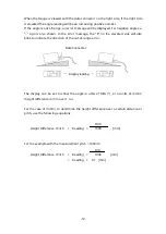
Page 12: ...levated side will also blink to indicate the direction of the out of range error The display can be set to show the angle in units of DEG or in units of mm m height difference in mm over 1 m For the case of mm m to determine the height difference over a certain distance or pitch use the following equations Pitch Height Difference Pitch Reading 1000 mm For the example with the measurement pitch 100...

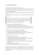
Page 13: ...tled press the 0 Cal Switch to set the display to zero A relative zero point has now been set for use in comparative angle measurements B If there is a true horizontal reference surface available 1 Place the Sensor on the surface to be used as the reference 2 When the display has settled press the 0 Cal Switch to set the display to zero Zero point has now been set for absolute measurements C If su...

Page 14: ...ethod even without a true horizontal reference we can determine the value of the angle 2 θ where θ is the angle of the slope in reference to the horizon By dividing by two we can determine θ the tilt of the slope If the gauge is set to zero on a slope then when the gauge is rotated 180 it will show the angle twice the actual tilt of the slope If the reading is then halved it will show the tilt of ...

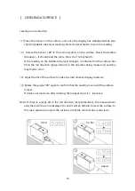
Page 15: ...ce has tilt in the roll direction perpendicular to the direction being measured and this may lead to error 3 Adjust the tilt of the surface to make the instrument s display read zero 4 Rotate the gauge 180 again to confirm that the reading is zero and the surface is level If it does not read zero after rotating then repeat steps 1 4 above Note If there is a large tilt in the roll direction perpend...

Page 16: ...epeat the procedure for the other direction the Y direction 3 When adjusting in one direction it is possible that the perpendicular direction will be affected and no longer level It may be necessary to repeat steps 1 2 several times to bring the two axis into level When the reading is zero for the level placed in any position the surface is level 16 ...

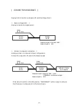
Page 17: ...e output DL P5 cable to the Data Out Jack If the Data In Switch is in the ON position NO CONNECT will be output to indicate that there was no data present on the Data In Jack 17 Display DL D3 Sensor DL S2 Display DL D3 Cable DL P1 5m Data Out Switch Neutral OFF Data In Switch OFF Sensor DL S2 Cable DL P1 5m Data Out Switch Neutral OFF OUT TERMINAL continuous output Data In Switch OFF DPU 411 Print...

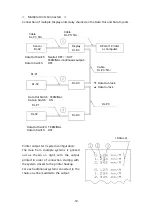
Page 18: ...with the system closest to the printer hookup For each additional system connected to the chain one line is added to the output 18 Cable DL P1 5m Cable DL P5 5m Display DL D3 DPU 411 Printer or Computer Sensor DL S2 Data Out Switch Neutral OFF OUT TERMINAL continuous output Data In Switch OFF DL P1 DL S2 Data Out Jack Data In Jack Cable DL P3 5m DL P1 DL S2 DL D3 DL P3 Data Out Switch TERMINAL Dat...

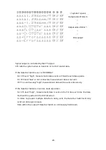
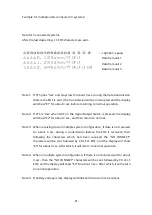
Page 19: ... manufacturer 1 TD Output Transmitted Data 2 CTS Input Clear to Send 3 GND Ground Comm method Asynchronous Comm Control Hardware CTS controlled Baud Rate 1200 bps Data Length 8 bit Stop Bits 1 Parity Bit No Output signal 5 V to 10 V Input Signal 3 V to 15 V Transmitted data will be 16 characters in each string Japanese character set In addition when the Data In Switch is OFF an EOF will be sent as...

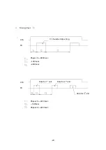
Page 20: ...f CTS is continuously high measurement data will be sent continuously If the Data Out Switch is in center neutral position For CTS level high measurement data is sent on the TD line each time the Data Out Switch is pushed in the OUT direction In order to prevent multiple data from being sent the Data Out Switch will only send out data upon release Data will not be output if Data Out Switch is cont...

Page 21: ...ltiple system configuration If data is not received for about 3 sec during a transmission before the EOF is received then following the characters which had been received the NO CONNECT characters will be sent followed by CR LF LF EOF and the display will show E3 for about 3 sec After which it will return to normal operation Note 4 When in multiple system configuration if there is no data received...

Page 22: ... Timing Chart 17 char data 22 85μsec to 400msec 140msec 400msec CTS TD CTS TD Data for 1st unit Data for 2nd unit Data for 3rd unit 85μsec to 400msec 140msec 85μsec to 400msec 17 character data string ...

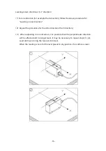
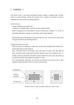
Page 23: ... outer body is larger than the base and will get stuck Shipping via Truck or Carrier Please prepare a shipping box with internal size approximately 20cm larger than the storage case in all dimensions Place the instrument in the storage case and place the case in the box with all sides protected with appropriate packing material such as shredded paper or similar cushioning material Pack with enough...

Page 24: ...riod remove batteries Store in cool dry location out of direct sunlight and protect from high humidity or severe temperature changes Keep away from magnets and strong magnetic fields When used in a support capacity for other equipment it can easily be damaged please use care to avoid scratches or corrosion Do not modify or use for purpose other than original intended use 24 ...

Page 25: ...r Continuous Use Time Zinc Carbon battery approx 27 hours 2 Alkaline battery approx 55 hours Dimensions 235 L 106 W 51 H mm Weight 1 0kg Accessories AC100V Adapter Storage Case Owner s Manual 1 When DEG is selected for display the O left of decimal is not shown 2 Some variation depending on usage conditions NIIGATA SEIKI CO LTD 6 15 22 Tsukanome Sanjo city Niigata 955 0055 JAPAN TEL 0256 31 5670 2...

Reviews: