background image


Contents

Important Information ·····························2
Warranty and Disclaimer ·························4
1.  Safety ·······················································5

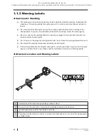
1.1  Warnings ····························································5
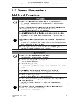
1.2  General Precautions ······································7
1.3  Safety Devices and Protective Guard ····15
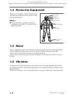
1.4  Protective Equipment ································16
1.5  Noise·································································16
1.6  Vibration ·························································16

2.  Outline ··················································17

2.1  Attached Material ·················································17
2.2  Model and Position of Serial No. ··················17
2.3  Name of Parts and Their Functions ······18
2.4  Specification ··················································19

3.  Installation and Adjustment ··············20

3.1  Assembly of Engine ····································20
3.2  Assembly of Handle ····································20
3.3  Installation of Split Attachment ·············21
3.4  Installation/Adjustment of Harness ·····22
3.5  Assembly of Terminal for Lead Wire ····24
3.6  Connection/Adjustment of Throttle Cable ··· 25
3.7  Adjustment of Idling Engine Speed ·····27

4.  Operation ············································28

4.1  Pre-operation Check ··································28
4.2  Start and Stop ···············································29
4.3  Precautions for Operation ························32
4.4  Actions after Operation·····························33

5.  Maintenance ······································34

5.1  Daily ··································································35
5.2  Every 20 Hours or 3 Months ····················36
5.3  50Every 50 Hours or 6 Months ···············37
5.4  Every 100 Hours or 1 Year ························38
5.5  Every 300 Hours or 2 Years ······················38

6.  Storing ··················································39
7.  Waste Disposal ··································40
8.  Troubleshooting ·······························41
9.  Service after Sales ·····························42
10. Technical data (EN31806) ··············43

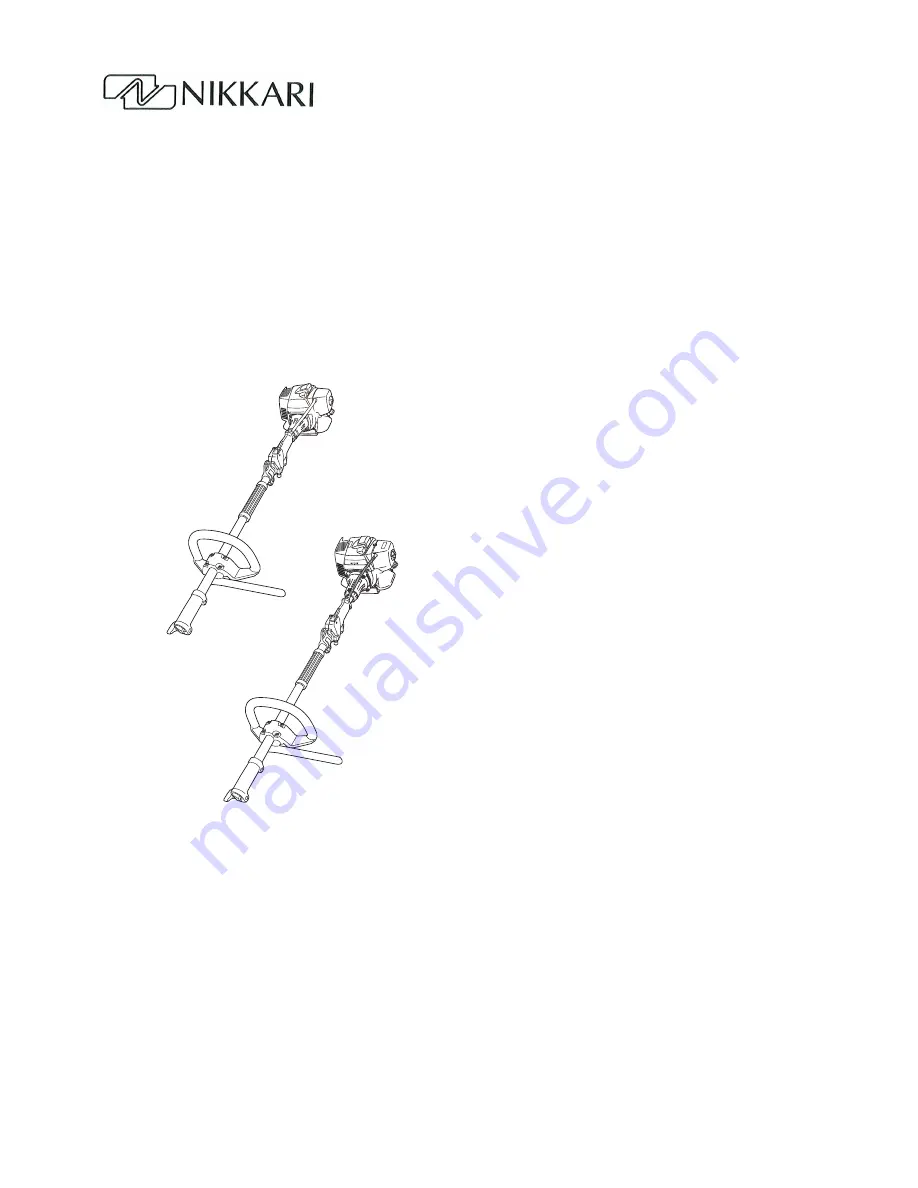
NIKKARI Split Engine

MJ-26K, MJ-35K

Instruction Manual

Copyright (C) 2010 NIKKARI Co., Ltd. All Rights Reserved

For Safe Use of Split Engine


Be sure to read this manual and the split attachment 
(to be purchased separately) manual to have a good 
understanding of the contents before handling the split 
engine.


If there is no split engine manual, purchase it from 
sales agency.


Keep this manual and the split engine manual carefully 
in a readily accessible location.

Original Instruction

This is a manual downloaded from the web site.

Explanation in the manual which comes together with your purchased product may differ from your product. Use the manual for reference.

Summary of Contents for MJ-26K

Page 1: ...ions after Operation 33 5 Maintenance 34 5 1 Daily 35 5 2 Every 20 Hours or 3 Months 36 5 3 50Every 50 Hours or 6 Months 37 5 4 Every 100 Hours or 1 Year 38 5 5 Every 300 Hours or 2 Years 38 6 Storing...

Page 2: ...plied in the purchase country assuming that the use is only limited to the case of use in the purchase country The split sytem is not designed or produced to comply with the standards or regulations o...

Page 3: ...rights are reserved This instruction manual in whole or part may not be copied translated or reproduced to any electronic medium or machine readable without prior written consent from NIKKARI The con...

Page 4: ...se by unqualified person misuse use of unspecified accessories and overload of the split engine Disclaimer NIKKARI will not be liable for any or all of the following failures or damages NIKKARI shall...

Page 5: ...rious injury CAUTION Indicates a potentially hazardous situation which if not avoided could result in minor or moderate injury CAUTION Indicates potentially hazardous situation which if not avoided co...

Page 6: ...ng labels Also do not clean the warning labels with solvent e Do not paint the warning labels when repainting the split engine f If the warning labels become illegible damaged or removed purchase new...

Page 7: ...erwise it could cause that the attachment to come off Do not use the split engine without the attachment Otherwise a serious accident or damage will happen Do not allow minors to operate this equipmen...

Page 8: ...for your cloths Otherwise it could cause injury 1 2 3 Precautions before Operation Do not allow children or animals to enter the working range of this equipment within 15m Otherwise a serious acciden...

Page 9: ...dge of the blade or cutter is blunt or damaged do not operate the split engine Otherwise it could cause damage to the engine and machine due to overloading 1 2 4 Precautions at Start up This equipment...

Page 10: ...e this equipment continuously for a long time If it is operated continuously for a long time vibration induced white finger could be developed Do not operate the this equipment by one hand You could d...

Page 11: ...et contact with people and objects around Otherwise it could cause a injury to the person or damage to objects by contact with the blade or cutter or the operator could fall down by the kickback of th...

Page 12: ...itation due to contact with the fuel or fire accident Before carrying out the maintenance stop the engine This equipment and the attachment have the driving part the high voltage part and the high tem...

Page 13: ...accident due to tripping over or falling could happen When transporting this equipment on the back of the truck discharge the fuel and fix this equipment tightly so that it does not move Otherwise thi...

Page 14: ...the fuel cap completely after refueling i Check if there is no oil leaking Because the fuel is highly combustible if mis handled there is a risk of fire Before refueling touch the ground or the metal...

Page 15: ...rigger lockout 2 is gripped Interlock system B Stop Switch When the stop switch 3 is set to OFF O side the engine will stop and the operation of blade cutter fan etc will stop However the blade will s...

Page 16: ...system frequently must undergo a hearing test However take care when wearing the ear protection equipment Your ability to hear shouts or alarms is restricted 1 6 Vibration Vibration generated by the s...

Page 17: ...Box wrench 2 2 Model and Position of Serial No This instruction manual is for split engine of model in same series Check the model of your split system on the nameplate attached to the machine body an...

Page 18: ...ing is the structure of the split system and name and function of each part 4 9 14 12 13 10 11 8 3 6 1 2 15 16 7 5 This is a manual downloaded from the web site Explanation in the manual which comes t...

Page 19: ...ovided Grip it with your right hand 9 Clutch housing Transmits the power from the engine to the power transmission shaft 10 Spark plug A plug to light the fuel gas in the engine cylinder The voltage a...

Page 20: ...rubber 2 to the shaft tube blade side from the distance collar 1 Set the handle loop bar 3 to the handle rubber 2 so that the barrier 4 should be on the left side Set the handle loop 5 from above Tigh...

Page 21: ...sult Be sure to use blades or cutters designated by the manufacturer If any blade or cutter other than that specified is used the blade or cutter could be damaged or it could come off resulting in inj...

Page 22: ...e procedure in 1 3 2 Safety Device Quick Release in an emergency Adjust the position with the engine stopped Wear the harness so that the waist pad hook 1 should be on your right side Adjust the lengt...

Page 23: ...split system Note Set the split system on the right side of operator Grip the handle to check the balance 3 4 This is a manual downloaded from the web site Explanation in the manual which comes toget...

Page 24: ...2 for lead wires of the engine side and control grip side Note If the terminals for lead wires are not connected completely the engine cannot be stopped with the stop switch 1 1 2 2 This is a manual...

Page 25: ...n Insert the throttle cable 1 into the bracket 2 Fix with the nut 2pcs from the both sides 2 1 1 2 Bracket Nut Throttole cable This is a manual downloaded from the web site Explanation in the manual w...

Page 26: ...le cable length is too long The engine will not reach the necessary power even at the full throttle position Adjust the throttle cable length with the cable adjusting nut If the throttle trigger canno...

Page 27: ...counterclockwise until the cutting device such as the blade and cutter or fan stops operating Note The following is the appropriate idling engine speed MJ 26K TJ27E 3000min 1 MJ 35K TJ35E 3000min 1 T...

Page 28: ...handle or engine is loosened c Check if there is no fuel leakage If there is a leakage contact the sales agency for repair If fuel is dropped on the floor etc during lubrication wipe it off Do not st...

Page 29: ...If the recoil starter is released the starter will be returned to the original position immediately and it could cause injury When starting the engine firmly grip the recoil starter grip Do not grip t...

Page 30: ...und the blower discharge port Slowly push the priming pump 2 several times until the fuel reaches the overflow tube yellow or pink fuel tube 1 Perform the following 1 Make sure that the engine is suff...

Page 31: ...djustment of Idling Engine Speed If the engine does not start do not frequently pull the starter with the choke closed Otherwise the cylinder will be filled up with the fuel making the start more diff...

Page 32: ...n addition to the above observe the cautions described in the split attachment manual Check of Work Area Take extreme care when operating in a slippery place Also watch out for rough ground stumps roo...

Page 33: ...the split system can be released from the harness by using the quick release 4 4 Actions after Operation After using the split system take the following actions Set the stop switch to OFF O side to st...

Page 34: ...3 Removal of foreign objects Refer to 5 1 4 Inspection of control grip Refer to 5 1 5 Backlash of throttle cable Refer to 5 1 6 Cleaning of air clean element Refer to 5 2 1 Cleaning of fuel filter Re...

Page 35: ...eign Objects Remove the foreign objects attached to the engine 5 1 5 Inspection of Control Grip Check if the throttle tripper and trigger lockout move smoothly If there is any failure contact the sale...

Page 36: ...eaner cap until the claw is securely fixed 5 2 2 Cleaning of Fuel Filter Drain the fuel from the fuel tank Pull out the fuel filter 1 from the fuel tank Clean the fuel filter with a clean gasoline Mak...

Page 37: ...the box wrench Clean the electrode with a spark plug cleaner or a wire brush Slightly screw the spark plug into the engine by hand Securely tighten it with the box wrench Securely insert the spark pl...

Page 38: ...gine will not rotate stably If there is any failure contact the sales agency 5 4 3 Check of Clutch If the clutch is worn the engine output will be reduced If there is any failure contact the sales age...

Page 39: ...s high in temperature Drain the fuel from the fuel tank and clean the tank Keep the engine operated until the carburetor is dried Stop the engine and store the split attachment and split engine in the...

Page 40: ...erve the standards and regulations of your region If there is any question contact the sales agency This is a manual downloaded from the web site Explanation in the manual which comes together with yo...

Page 41: ...ntact the sales agency Mixing failure of fuel Refer to 4 2 1 Start Vibration is too large Cuttingdevicesuchasbladeand cutteriscrackedorbroken Contact the sales agency Screws nuts at the handle mountin...

Page 42: ...pair If there is any problem try finding the cause and take measures according to 8 Troubleshooting If it does not solve the trouble contact the sales agency Contact for Repair Contact the sales agenc...

Page 43: ...formance Engine speed in accordance with ISO 8893 kW min 1 0 9 7500 1 2 7000 Maximum rotational frequency of the spindle min 1 8000 8500 Engine speed rotational frequency at idling min 1 3000 3000 Spe...

Page 44: ...MJ 26K MJ 35K E3499 0 44 September 2010 This is a manual downloaded from the web site Explanation in the manual which comes together with your purchased product may differ from your product Use the m...

Reviews: