background image

NL

10

10-35x

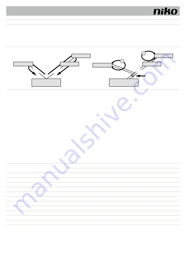
Principe van de lijnweerstand

Lijnweerstand meten

De buitenpost, binnenpost of de functie-uitbreiding mag nooit meer dan 
20 Ω van het voedings- en besturingsapparaat zijn verwijderd.

De meting uitvoeren:

 Schakel de 230 V / 50 Hz van het voedings- en besturingsapparaat uit. 
 Geef het voedings- en besturingsapparaat een a/b-kortsluiting.
 Andere toestellen store n de meting niet en mogen aangesloten blijven.
 Meet aan de laatste binnen- of buitenpost van de lijn de weerstand aan a/b.

a/b hier kortsluiten

a/M

Binnenpost

Binnenpost

Binnenpost

Binnenpost

b/P

Voedings- en

besturingsapparaat

Voedings- en

besturingsapparaat

Buitenpost

Buitenpost

Ohm

Ohm

maximaal 2

0 Ω

maximaal 20 

Ω

a/b

, P/M

a/b

, P/M

Regel voor 20 Ω:

Afstand van bus-voeding tot verst verwijderde buiten- of binnenpost: 
• 

bij diameter 

van 0,6 mm 

maximaal 160 m

• 

bij diameter

 van 0,8 mm 

maximaal 280 m

11.3.  Video-installaties   

11.3.1. 

Werking met 6 draden

• De werking met 6 draden geldt als standaardmodus. Videomodus, waarbij twee gescheiden massakabels (b en M) worden gebruikt.
• Hoe de kabels lopen, hangt af van omstandigheden in het gebouw. De lengte van de kabels is daarbij bepalend.
• Houd bij de keuze van de lengte van kabels op de max. lijnweerstand van 8 Ω (a-b en M-P).
• Bij een lijnweerstand > 8 Ω moeten er voor de lijnen meer kabels worden voorzien (verdraaide kabels dubbel).
• U kunt kiezen om kabels in lijn of in stervorm te leggen.
• Zet niet meer dan 20 videobinnenposten op één lijn. Voorzie voor installaties met meer videobinnenposten ook videoverdelers.
•  Op één installatie kunnen tot 64 buitenposten (waarvan 16 videobuitenposten) en zo goed als een onbeperkt aantal binnenposten zonder polariteit (a/b) worden 

aangesloten (enkel in geval van een werking met 6 kabels). Hiervoor moet u wel met een geschikt voedings- en besturingsapparaat werken.

11.3.2. 

Tabel: lijnweerstanden video-installaties

Draadlengte a-b / M-P

in m

Diameter van draden

0,6 mm

0,8 mm

Lijnweerstand in Ω

10

1,28

0,71

20

2,55

1,43

30

3,83

2,14

40

5,10

2,86

50

6,38

3,57

60

7,65

4,29

70

5,00

80

5,71

90

6,43

100

7,14

Summary of Contents for 10-35 Series

Page 1: ...ionele modules in buitenposten pour kit d encastrement pour modules fonctionnels dans les postes ext rieurs f r Unterputzmontageset f r Funktionsmodule in Au enstationen for ush mounting set for funct...

Page 2: ...10 35x 02 Nederlands 13 Fran ais 23 Deutsch 33 English 43 Sloven ina...

Page 3: ...e risicograad dat indien het niet wordt vermeden dodel ke gevolgen heeft of tot zware letsels leidt WAARSCHUWING Dit signaalwoord duidt op een gevaar met een gemiddelde risicograad dat indien het niet...

Page 4: ...t zich niet aansprakel k voor andere dan de voorziene toepassingen of toepassingen die het beoogd gebruik overst gen 5 ORDENING VAN DE MODULES 5 1 Inbouwposities voor modules in een buitenpost Meer ge...

Page 5: ...al in g 10 351 200 x 200 x 3 180 x 180 x 50 1 400 10 352 320 x 200 x 3 300 x 180 x 50 2 090 10 353 440 x 200 x 3 420 x 180 x 50 2 780 10 354 560 x 200 x 3 540 x 180 x 50 3 480 10 355 680 x 200 x 3 660...

Page 6: ...eleverd 2 1 3 Frontplaat Afb 3 Frontplaat 7 2 Module in frontplaat speciale constructie inbouwen zodat deze vooraan aansluit Om de functionele module vooraan aansluitend in te bouwen moet de inbouwdie...

Page 7: ...zonken kop M4 x 30 van de frontplaat los met de zeskant inbussleutel Open de inbouwset Draai de moeren M3 van de geleideplaten los detail afb 5 Haal de frontplaat van de inbouwcassette Trek de voeding...

Page 8: ...de inbouwcassette Bevestigdegeleideplatenmetdemoeren M3 Draaidemoeren nog niet helemaal vast Scheef geplaatste inbouwcassettes kunnen met een maximale tolerantie van 15 mm diep rechter op de geleidep...

Page 9: ...0 zie de tabel hieronder Om de max lijnweerstand niet te overschrijden kunt u de doorsnede van de aders verdubbelen Dit betekent dat u voor nadertweekabelsgebruikt afbeelding22 Dekabelsmoeten in elkaa...

Page 10: ...werking met 6 draden geldt als standaardmodus Videomodus waarb twee gescheiden massakabels b en M worden gebruikt Hoe de kabels lopen hangt af van omstandigheden in het gebouw De lengte van de kabels...

Page 11: ...ge doek Verwijder hardnekkig vuil met een pH neutraal reinigingsmiddel Plexiglas W raden aan om het kunststof met een antistatisch reinigingsmiddel voor kunststof te reinigen om zo de stofwerende werk...

Page 12: ...er het gebrek aan overeenstemming en dit uiterl k binnen de twee maanden na vaststelling In geval van een gebrek aan overeenstemming heeft de consument enkel recht op een kosteloze herstelling of verv...

Page 13: ...n danger pr sentant un haut degr de risque ayant s il n est pas vit des cons quences mortelles ou provoquant de graves l sions AVERTISSEMENT Cette mention d avertissement indique un danger pr sentant...

Page 14: ...un endroit le moins expos possible aux rayons directs du soleil Le fabricant n assume aucune responsabilit pour d autres applications que celles pr vues ni pour des applications s cartant de l usage v...

Page 15: ...poids Article Plaque frontale Cassette d encastrement Poids H x B x D en mm H x B x D en mm total en g 10 351 200 x 200 x 3 180 x 180 x 50 1 400 10 352 320 x 200 x 3 300 x 180 x 50 2 090 10 353 440 x...

Page 16: ...tale Fig 3 Plaque frontale 7 2 Encastrer le module dans la plaque frontale construction sp ciale de mani re ce que celle ci se raccorde par l avant Pourencastrerlemodulefonctionnel l avantdemani rejoi...

Page 17: ...frontale l aide de la cl Allen hexagonale Ouvrez le kit d encastrement Retirez les crous M3 de la plaque de guidage d tails la Fig 5 Enlevez la plaque frontale de la cassette d encastrement Tirez le...

Page 18: ...castrement Fixezlesplaquesdeguidage l aidedes crous M3 Neserrez pas encore compl tement les crous Les cassettes d encastrement plac es avec une certaine inclinaison peuvent tre redress es sur les plaq...

Page 19: ...r le tableau ci dessous Pour viter de d passer la r sistance de ligne maximale vous pouvez doubler la section des conducteurs Cela signifie que vous utilisez deux c bles pour un conducteur Fig 22 Les...

Page 20: ...ils Le fonctionnement avec 6 ls est le mode standard Mode vid o faisant usage de deux c bles de terre b et M distincts Le cheminement des c bles d pend des caract ristiques de l immeuble La longueur d...

Page 21: ...sion sur les composants lectroniques vitez toute p n tration d eau ou de produits d entretien dans l appareil ATTENTION D g ts la surface de l appareil N utilisez pas de produits d entretien agressifs...

Page 22: ...date de la facture d achat par le consommateur est consid r e comme la date de livraison En l absence de facture la date de fabrication est valable Le consommateur est tenu de pr venir Niko par crit d...

Page 23: ...Gef hrdung mit einem hohen Risikograd die wenn sie nicht vermieden wird den Tod oder eine schwere Verletzung zur Folge hat WARNUNG Das Signalwort bezeichnet eine Gef hrdung mit einem mittleren Risikog...

Page 24: ...sehr hei werden mehr als 50 C Vermeiden Sie m glichst bei der Auswahl des Montageortes eine direkte Sonneneinstrahlung DF r Anwendungen die vom bestimmungsgem en Gebrauch abweichen oder ber diesen hi...

Page 25: ...200 x 200 x 3 180 x 180 x 50 1 400 10 352 320 x 200 x 3 300 x 180 x 50 2 090 10 353 440 x 200 x 3 420 x 180 x 50 2 780 10 354 560 x 200 x 3 540 x 180 x 50 3 480 10 355 680 x 200 x 3 660 x 180 x 50 4...

Page 26: ...ungsmuttern 3 im Lieferumfang enthalten 2 1 3 Frontplatte Abb 3 Frontplatte 7 2 Modul in Frontplatte Sonderbau frontb ndig einbauen Bei einer Frontplatte mit geringerer Materialst rke von 1 5 bis 2 5...

Page 27: ...kelschraubendreher ffnen Sie die Unterputzkasten L sen Sie die Muttern M3 der F hrungsbleche Detail Abb 5 Nehmen Sie die Frontplatte vom Unterputzkasten ab F hren Sie das Versorgungskabel durch die Ka...

Page 28: ...ieF hrungsblechemitdenMuttern M3 Ziehen Sie die Muttern noch nicht fest an Ungleichm ig eingebaute Unterputzk sten k nnen bis zu einer Toleranz von max 15 mm Tiefe mit den F hrungsblechen ausgeglichen...

Page 29: ...Tabelle unten Zur Einhaltung des max zul ssigen Schleifenwiderstandes kann der Aderquerschnitt verdoppelt werden das hei t f r eine Ader werden zwei Leitungen verwendet Abb 9 Die Leitungen sind zu ver...

Page 30: ...r 6 Drahtbetrieb ist Standardbetriebsart Videobetrieb bei dem zwei getrennte Masseleitungen b und M verwendet werden Die Leitungsf hrung wird durch die baulichen Gegebenheiten bestimmt und ist nur dur...

Page 31: ...iden Sie das Eindringen von Wasser und Reinigungsmitteln in das Ger t ACHTUNG Besch digung der Ger teober che Verwenden Sie keine aggressiven und kratzenden Mittel zur Reinigung der Ober che Reinigen...

Page 32: ...traum betr gt vier Jahre ab Lieferdatum Als Lieferdatum gilt das Rechnungsdatum zum Zeitpunkt des Kaufs durch den Endverbraucher Falls keine Rechnung mehr vorhanden ist gilt das Produktionsdatum Der E...

Page 33: ...word Explanation DANGER This signal word indicates a high degree of risk which if not avoided will result in fatal consequences or serious injury WARNING This signal word indicates an moderate degree...

Page 34: ...direct sunlight is kept to a minimum The producer is not liable for applications other than the ones foreseen or applications which exceed the intended use 5 MODULE ARRANGEMENT 5 1 Flush mounting posi...

Page 35: ...sions and weight Article Front plate Flush mounting cassette Weight H x W x D in mm H x W x D in mm total in g 10 351 200 x 200 x 3 180 x 180 x 50 1 400 10 352 320 x 200 x 3 300 x 180 x 50 2 090 10 35...

Page 36: ...3 included 2 1 3 Front plate Image 3 Front plate ZAU 7 2 Flush mount module in front plate special construction so that it is adjacent at the front To ush mount the functional module in an adjacent ma...

Page 37: ...ntersunk screws M4 x 30 from the front plate using the hexagonal key Open the flush mounting set Loosen the bolts M3 from the guide plates detail image 5 Remove the front plate from the flush mounting...

Page 38: ...he guide plates using the nuts M3 Do not completely tighten the nuts yet Crookedly placed ush mounting cassettes can be adjusted onto the guide plates with a maximum tolerance up to 15 mm deep Slide t...

Page 39: ...um line resistance of 20 see table below Tokeepwithinthemax permissiblelineresistancetheconductor cross section can be doubled This means that two cables are usedforoneconductor image22 Thecablesmustb...

Page 40: ...its 11 3 1 6 wire operation The 6 wire operation is standard Video mode in which two separated earth cables b and M are used The course of the cables depends on the buildings conditions It depends on...

Page 41: ...ing into the device may cause short circuits and corrosion of electronic com ponents Prevent water or detergents seeping into the device ATTENTION Damage to the surface of the device Do not use aggres...

Page 42: ...om the date of delivery The delivery date is the invoice date of purchase of the product by the consumer If there is no invoice the date of production applies The consumer is obliged to inform Niko in...

Page 43: ...bude s istotou ma za n sledky usmrtenie alebo v ne poranenie os b VAROVANIE Toto v stra n slovo indikuje stredn riziko ktor mu ke nezabr nite tak m e ma za n sledky usmrtenie alebo v ne poranenie os b...

Page 44: ...zapusten mont modulov do externej jednotky Podrobnej ie inform cie o jednotliv ch moduloch n jdete v technickom liste produktu s n zvom Funk n moduly na internete v asti pre pl novanie produktov a v...

Page 45: ...H v mm celkovo v g 10 351 200 x 200 x 3 180 x 180 x 50 1 400 10 352 320 x 200 x 3 300 x 180 x 50 2 090 10 353 440 x 200 x 3 420 x 180 x 50 2 780 10 354 560 x 200 x 3 540 x 180 x 50 3 480 10 355 680 x...

Page 46: ...a 2 1 3 Predn kryt Obr 3 Predn kryt ZAU 7 2 Mont z pustn ho modulu do predn ho krytu peci lna kon trukcia aby priliehal k predku Ak chcete zapusti funk n modul tak aby k predku priliehal tak mus te z...

Page 47: ...z pustn skrutky M4 x 30 z predn ho krytu Otvorte s pravu na zapusten mont Uvo nite skrutky M3 nach dzaj ce sa na vodiacich li t ch detail na obr 5 Z krabice na zapusten mont odstr te predn kryt Cez pr...

Page 48: ...ujte vodiace li ty pomocou mat c M3 Skrutky e te plne nedo ahujte Nakrivo namontovan krabice na zapusten mont m ete upravi pod a vodiacich l t s maxim lnou h bkovou toleranciou do 15 mm Zasu te vodiac...

Page 49: ...por vedenia 20 vi ni ie uveden tabu ku Aby bol dodr an max pr pustn odpor vedenia tak m ete prierez vodi a zdvojn sobi To znamen e v jednom vodi i s pou it dva k ble obr 22 K ble musia by kr ten Pri p...

Page 50: ...mere 0 8 mm 11 3 Video s pravy 11 3 1 6 vodi ov technika 6 vodi ov technika je tandardn Video re im v ktorom s pou it dva samostatn uzemnen vodi e b a M Vedenie k blov z vis od podmienok stavby Z vis...

Page 51: ...prostriedky m e nasta vyskratovanie a kor zia t chto komponentov Nedovo te vode a istiacim prostriedkom prenikn do zariadenia UPOZORNENIE Po kodenie povrchu zariadenia Na istenie povrchu nepou vajte...

Page 52: ...je tyri roky od d tumu dod vky Za d tum dod vky sa pova uje d tum faktur cie alebo vydania in ho da ov ho dokladu z kazn kovi Ak tak to doklad nie je k dispoz cii plat d tum v roby Z kazn k je povinn...

Reviews: