37
EN
10-35x
8. MOUNTING OF THE FLUSH-MOUNTING SET 10-35X
8.1. Make a hole in the wall
The hole in the wall must be large enough that it will fit the external dimensions of the flush-mounting cassette with a tolerance of:
•
In circumference (HxW) min + 0.5 mm up to max + 5 mm and
•
Depth (D) min + 0.0 mm up to max + 15 mm.
For example:
External dimensions flush-mounting cassette (HxWxD):
540 x 180 x 50 mm
Hole in the wall (HxWxD):
min. 541 x 181 x 50 mm and max. 550 x 190 x 65 mm
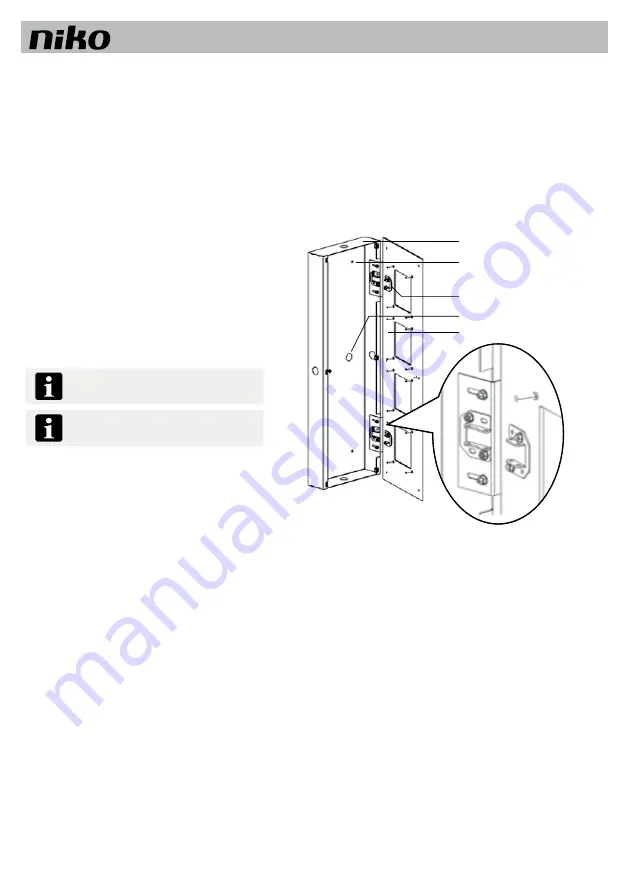
8.2. Mounting flush-mounting cassette
Loosen countersunk screws (M4 x 30) from the front plate
using the hexagonal key.
Open the flush-mounting set.
Loosen the bolts (M3) from the guide plates (detail image 5).
Remove the front plate from the flush-mounting cassette.
Pull the power supply cable through the cable run into the
flush-mounting cassette and fix it into place.
Place the flush-mounting cassette in the hole in the wall.
Fix the flush-mounting cassette into place using the suitable
mounting equipment.
Screws and plugs to mount the flush-mounting
cassette are not included.
Pay attention to the sizes (see Make a hole in
the wall).
Flush mouting cassette
Drill holes for screws
Hinge
Cable feedtrough
Front plate
Image 5: Mounting flush-mounting cassette


