4(8)
Servodan A/S | Tel +45 7442 4726 | Fax + 45 7442 4035 | info@servodan.dk | www.servodan.com
41Y773_03_R1_131104CWH
GB
User manual
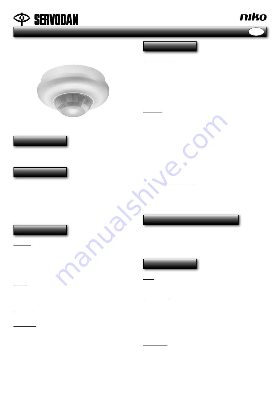
Motion detector 8 m high ceiling,
slave, 41-773
Use
The motion detector 360° slave is used together with
41-771, for widening the detection range.
Function
It is possible to connect 10 slave detectors (41-773) to one
41-771 (master) which will control the load with its settings.
Master and slave motion detectors have the same range.
To achieve complete coverage by using several detectors,
it is recommended that an overlap of approximately 30% is
calculated.
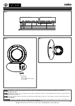
Fig. 1.
Installation
Location:
The detector responds to movement and heat in relation to the
surroundings. Avoid placing the detector close to heat sources
such as ventilation systems, or moving objects. This may
cause unwanted activation. If installed in warehouses where
closed trucks are used, reduced functionality may occur due to
differences in temperature being so slight.
Fig. 2.
Range:
The recommended installation height for this detector is 4-8 m.
At this height the detector has a range of Ø 16-32 m (without the
lens cover).
Fig. 3.
Installation:
The detector is designed for mounting on the ceiling.
Fig. 4.
Connection:
The detector must only be connected to a power supply once all
wire connections have been connected.
After connection to the power supply, the detector will be ready
to operate after approximately 40 seconds (warm-up time). The
red LED flashes for 0.25 seconds on and for 2 seconds off during
warm-up. The end of the warm-up time is indicated with two
short flashes from the green LED.
For wiring diagram,
Fig. 5.
Setting
Factory settings:
Fig. 6
Sensitivity: High sensitivity
DIP Sensitivity setting:
Off Off Minimum sensitivity
Off On Low sensitivity
On Off High sensitivity
On On Maximum sensitivity
Walk-test:
A walk-test can be carried out to check that the detector is
detecting correctly.
Select walk-test via the Time potentiometer (minimum position).
Fig. 7
When the walk-test is activated, the blue LED switches on,
and when the detector detects movement, the red LED and
connected lighting will switch on for five seconds. The blue LED
is inactive when the connected lighting is on.
NB! The walk-test is daylight
-independent
.
Setting via potentiometers:
The potentiometer has one function: Test
In order to activate the test, turn the potentiometer to the
minimum position. After the test has been completed, return the
potentiometer to the medium position.
Operation & maintenance
Dirt affects the operation of the detector and the detector’s lens
must therefore be kept clean. Use a damp cloth for cleaning. Use
water mixed with ordinary detergent. Avoid putting pressure on
the lens. If the lens or other parts of the detector are defective, it/
they must be replaced.
Technical data
Input:
Power supply ............................................. 230 V AC 50 Hz ±10%
Power consumption .................................. 0.2 W
Performance:
Potentiometer ............................................ for test
Range ........................................................ Ø 16-32 m, 360°
Installation height ...................................... 4-8 m
Sensitivity ................................................. 4 settings
Enclosure class ......................................... IP 54
Cable dimension (Ø14 mm max.) .............. 3 pcs. 5 x 2.5 mm
²
Ambient temperature ................................. -5°C to +50°C
Certification:
CE in accordance with .............................. EN 60669-2-1
The detector is delivered with a lens cover - can be
adapted or removed for correct coverage.


