JAA80551-R.3757.A
- 6・AF-S DX 8-05/3.5-5.6G ED VR -
Main PCB unit
・
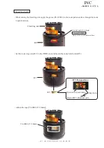
Make a preliminary soldering on the main PCB unit (B1001), [only when the GND lead wire (#1020) is
replaced.)
Pre-soldering
・
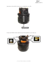
Solder the GND lead wire (#1020) on the main PCB unit (B1001), [only when the GND lead wire (#1020)
is replaced.)
#1020
B1001
・
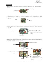
Mount the main PCB unit (B1001) by fitting the protrusion of the fixed ring unit in the hole of the main PCB
unit (B1001), then tighten the two screws (#126).
B1001
B1001
Surface for positioning
Place the GND lead wire
(#1020) behind the main PCB
unit.
#126
#126
Hole
Hole
Surface for positioning
B1001
Attach by aligning the rim of the
connector A and the four soldering
positions.
TA-0020 (8×8mm)
・
Adhere the tape [TA-0020 (8×8mm)] to the main PCB unit (B1001), [only when the main PCB unit (B1001)
is replaced].
Connector A
INC


