JAA80551-R.3757.A
- 33・AF-S DX 8-05/3.5-5.6G ED VR -
3.Adjustment
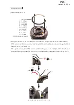
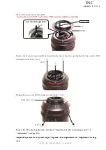
Adjustment during assembly
When the GMR unit is disassembled or replaced, be sure to make inspection and adjustment.
1. Device
・
Single-output rated voltage power-supply 1 unit : 5V , 100mA
・
Oscilloscope 1 unit
・
GMR-output inspection tool 1 unit (Self-made tool)
Refer to the below "2. Creation of GMR-output inspecting tool" (on Page A33) for details.
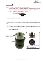
Caution: In case the relay-FPC contact surface is stained, eroded, or oxidized, it will cause a failure of
conduction between the GMR output inspection tool and the relay-FPC contact. So polish the
contact and connect them.
Inspection and Adjustment of GMR output waveform
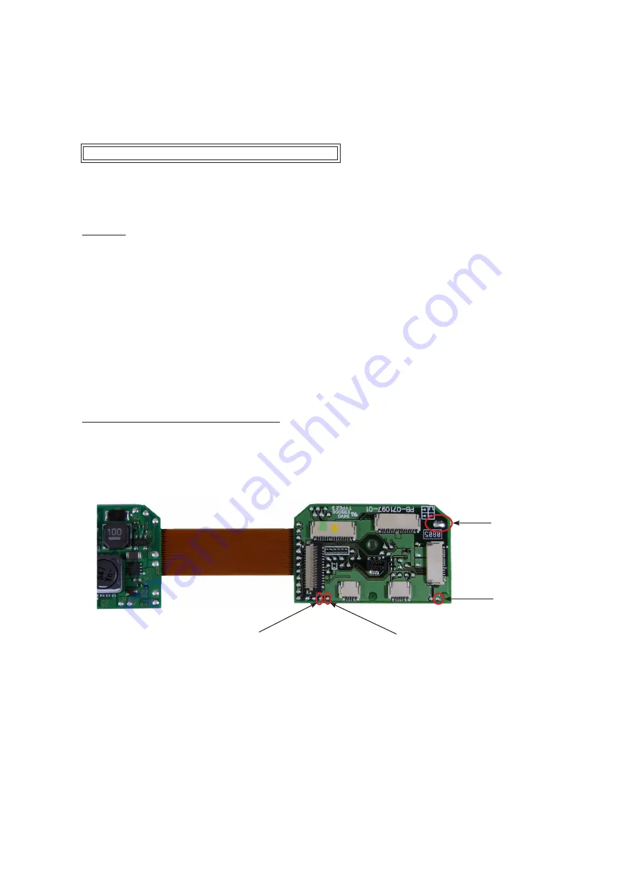
2. Creation of GMR-output inspecting tool
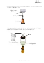
For inspecting and adjusting the GMR output waveform, creating a self-made tool by using the main PCB
(1S020-557) is necessary as follows:
Solder the wires on the four patterns of the PCB as follows.
GND
Constant voltage
power supply (+)
Oscilloscope (2ch)
Oscilloscope (1ch)
INC

