background image

JAA80351-R.3739.A

- ・AF-S DX 8-55/3.5-5.6G VR -

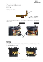
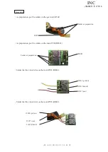
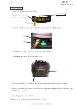
Contact pin unit

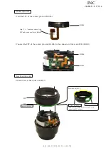
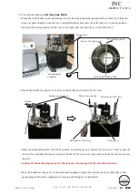
Fold the FPC of the contact pin unit (B1006).

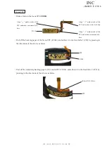
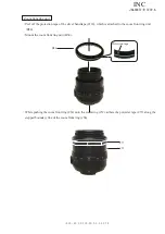
Rear fixed tube unit

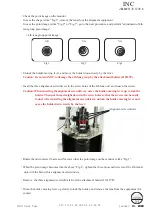
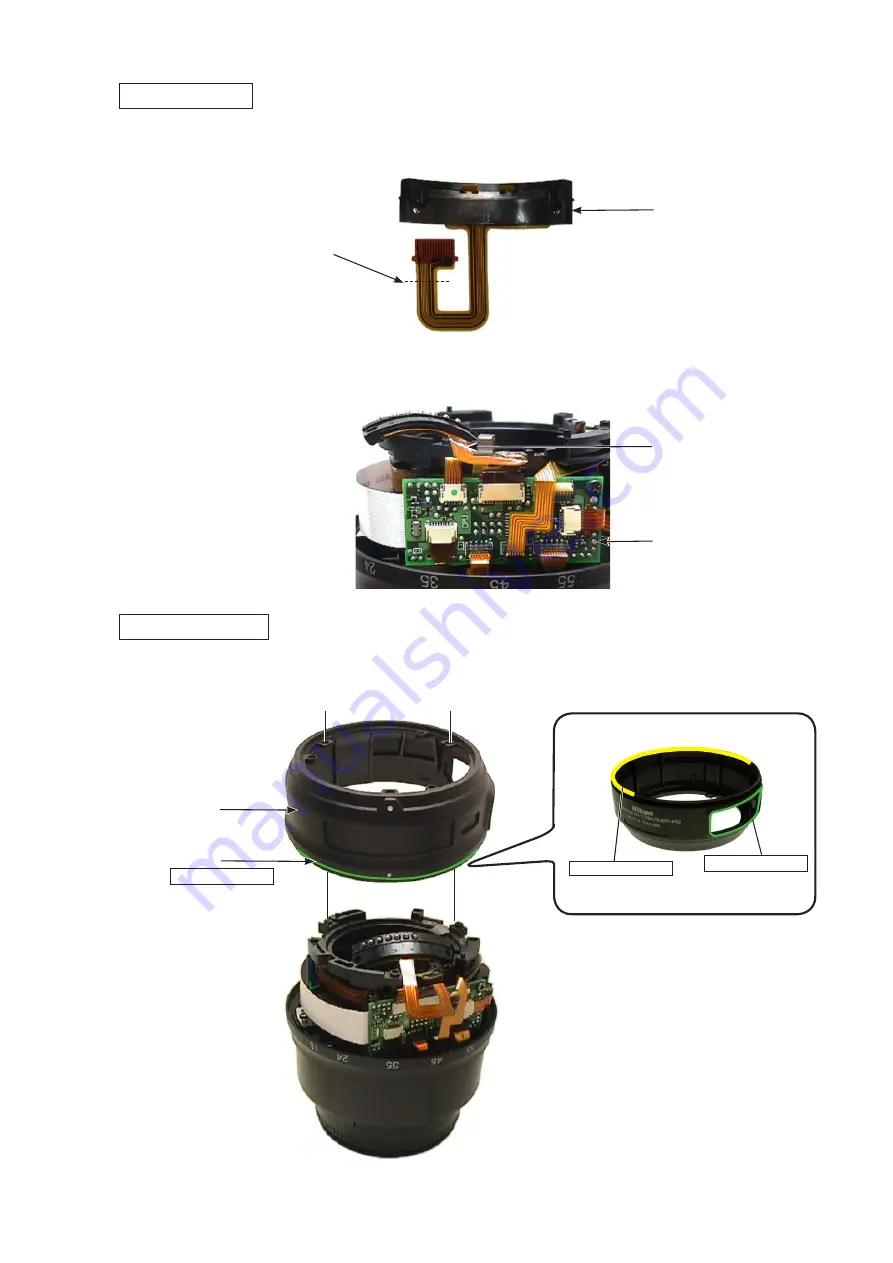
M��unt t�e rear fixed tube unit (B57).

Grease:OS-30MEL

B57

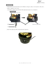
B1006

B1001

B1006

#64

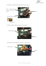
Connect the FPC of the contact pin unit (B1006) to the connector of the main PCB (B1001).

Align "

" marks at ends of the 

FPC and make a valley-fold here.

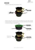
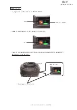
Appl�� t�� t�e slidin�� surface except t�e area 

around the SW window.

Bottom of [B57] 

Grease:MZ-800SEL

Grease:OS-30MEL

INC

Summary of Contents for AF-S DX Nikkor 18-55mm/F3.5-5.6G VR

Page 1: ...作成承認印 配布許可印 JAA80351 R 3739 A JAA80351 Copyright c 2007 by Nikon Corporation All Rights Reserved 無断転載を禁ず Printed in Japan November 2007 AF S DX Nikkor 18 55mm F3 5 5 6G VR REPAIR MANUAL M サービス 計画課 INC ...

Page 2: ...h lens group unit This lens also has the VR vibration reduction unit mounted in order to correct camera shake To keep the accuracy of this function for stabilizing the image in case the gyro FPC main PCB or the fixed tube unit VR unit is replaced be sure to make the VR adjustment by using the VR lens adjustment equipment J15380 However except for disassembling the above components the VR adjustmen...

Page 3: ...ve the company name ring 113 113 Remove the name plate 68 and VR name plate 69 69 68 Caution Removing the name plate 68 and VR name plate 69 are NOT necessary except when they are replaced 1 Disassembly Company name ring Name plate VR name plate INC ...

Page 4: ... 3739 A AF S DX 18 55 3 5 5 6G VR Remove the rubber ring 62 by pulling towards the 1st lens group side 62 91 39 91 91 Rubber ring Take out the three screws 91 and remove the rear cover ring 39 Rear cover ring INC ...

Page 5: ...F S DX 18 55 3 5 5 6G VR Set the zoom to WIDE end or TELE end Turn the 1st lens G unit B40 counterclockwise Then remove the washer 119 selected from A to I and the 1st lens G unit B40 38 B40 119A I 1st lens group unit INC ...

Page 6: ...e the 4th lens G unit B46 4th lens group unit B46 143 3 177 3 Caution The lens alignment work will be necessary after assembly in case the 4th lens G unit is removed At repair service facilities therefore where such alignment work can not be performed do NOT remove the 4th lens G unit Zoom front ring unit Peel off the polyester tape 77 77 INC ...

Page 7: ... 6G VR B54 Remove the zoom front ring 54 Set the M A switch to A side and take out the screw 155 B1013 155 B152 B152 Change SW unit Lift the black part of the connector of the PI FPC B1013 and remove the FPC of the change SW unit B152 INC ...

Page 8: ...lead wire 1027 from the PI FPC B1013 B1013 1027 GND lead wire Take out the three screws 78 and remove the bayonet mount unit B30 B30 78 3 Bayonet mount unit Take out the two screws 67 67 67 B1006 Addition Addition Changed page 2 December 10 2007 M サービス 計画課 INC ...

Page 9: ...JAA80351 R 3739 A AF S DX 18 55 3 5 5 6G VR Remove the washer 101 selected from A to I 101A I Rear fixed tube unit Remove the rear fixed tube unit B57 B57 INC ...

Page 10: ...CB unit Zoom FPC 1007 Focus FPC 1014 Hall element FPC B1005 PI FPC B1013 Gyro FPC B1004 Main VCM FPC 1009 179 SWM FPC Remove the FPC of the contact pin unit B1006 from the main PCB B1001 B1001 B1006 Contact pin unit Detach the SWM FPC from the double stick tape 179 of the fixed tube 1 29 INC ...

Page 11: ...10 AF S DX 18 55 3 5 5 6G VR Gear unit A Take out each screw 131 and 132 and remove the gear unit B501 Caution Do NOT touch A area 131 B501 132 Take out the two screws 145 and remove the main PCB B1001 B1001 145 145 INC ...

Page 12: ...ter ring 38 clockwise The keys of the segment gear tube 26 will be extended outwards so release them from the key grooves of the filter ring 38 and remove the filter ring 38 38 Key of 26 Zoom brush unit Take out the screw 102 and remove the zoom brush unit B85 B85 102 INC ...

Page 13: ...JAA80351 R 3739 A 12 AF S DX 18 55 3 5 5 6G VR Take out the two screws 103 and remove the zoom coupling key 61 Zoom ring 61 103 2 52 Set the zoom ring 52 to TELE end Lift and remove the zoom ring 52 INC ...

Page 14: ...JAA80351 R 3739 A 13 AF S DX 18 55 3 5 5 6G VR Focus brush unit Take out the screw 96 and remove the focus brush unit B97 96 B97 INC ...

Page 15: ...ve SX720B Zoom FPC Peel off the backing paper of the zoom FPC 1007 and adhere it to the fixed tube 2 28 by pressing in the directions of the arrows as below Peel off the backing paper of the gyro FPC B1004 and adhere it by pressing in the directions of the arrows as below 2 Assembly Adjustment Align marks of the FPC and make a valley fold here INC ...

Page 16: ...cking paper of the focus FPC 1014 and adhere it to the fixed tube 2 28 by pressing in the directions of the arrows as below Peel off the remaining backing paper of the zoom FPC 1014 and adhere it to the fixed tube 2 28 by pressing in the directions of the arrows as below Align marks at ends of the FPC and make a mountain fold here Align marks at ends of the FPC and make a mountain fold here INC ...

Page 17: ...ong the surface of the fixed tube 2 28 then attach it Tighten the screw 96 Attach B97 so that the tips of the brush R rounded parts touches the overall pattern Grease PL 22SEL Apply to the overall focus pattern surface 96 B97 Direction for positioning 28 26 Rotate the segment gear tube 26 and check the operations INC ...

Page 18: ...of 28 that is near the zoom pattern Then turn the zoom ring 52 counterclockwise Grease MZ 800SEL Grease MZ 800SEL 52 Apply to the overall surface sliding with 28 Apply to the overall sliding surface of groove Outside concave position of 28 Grease MZ 800SEL Attach the two cushion rubbers 56 to the fixed tube 2 28 56 28 56 Adhesive SX720B Adhesive SX720B Zoom ring Apply to the overall surface slidin...

Page 19: ... the key hole of the cam tube 50 Tighten the two screws 103 in numeric order from to and fixate the zoom coupling key 61 61 103 2 Key hole of 50 Position for attaching zoom coupling key of 52 Align the position for attaching the zoom coupling key of the zoom ring 52 with the key hole of the cam tube 50 INC ...

Page 20: ... tips of the brush R rounded parts are lined up with mark then attach it Tighten the screw 102 When B85 is attached cover a sheet etc approx 2 2cm over the pattern so as not to bend the brush B85 102 mark Grease PL 22SEL Apply to the overall surface of zoom pattern 52 Sheet etc Rotate the zoom ring 52 and check the operations INC ...

Page 21: ...bove mark of the helicoid ring 25 with the mark of the filter ring 38 and put the filter ring 38 into 25 Filter ring Grease MZ 800SEL 25 38 End of convex portion Mark Apply to the overall inside Key groove of 38 Key of 26 While turning the filter ring 38 clockwise put the key of the segment gear tube 26 into the key groove of the filter ring 38 INC ...

Page 22: ...e gear unit B501 B501 B2001 Solder as preparation 1027 red 1028 yellow 1029 black 1027 red 1028 yellow 1029 black Solder the three lead wires on the main PCB B2001 Solder the three lead wires on the main PCB B2001 As preparation put the solders on the main PCB B2001 Solder as preparation INC ...

Page 23: ...unit B501 Be careful NOT to touch A area 131 B501 132 Grease MZ 800SEL Apply to the overall surface 513 B501 A Assemble the gear unit B501 Tighten the screw 131 first and then the screw 132 to fixate B501 Before the fixation position the gear unit B501 towards the left direction INC ...

Page 24: ... 145 Direction for positioning 179 SWM FPC Gyro FPC B1004 Focus FPC 1014 PI FPC B1013 Connect the gyro FPC B1004 zoom FPC 1007 and PI FPC 1009 to each connector of the main PCB B1001 Adhere the double stick tape 179 to the fixed tube 1 29 and peel off the backing paper Then attach the SWM FPC Direction for positioning INC ...

Page 25: ...ctor 1014 Folding line position B1005 Folding line position 1009 Make a fold along the edge line of this Fold the hall element FPC B1005 and connect it to the connector Fold the focus FPC 1014 and connect it to the connector Align marks at the ends of the FPC and make a mountain fold here Edge line INC ...

Page 26: ...nt the rear fixed tube unit B57 Grease OS 30MEL B57 B1006 B1001 B1006 64 Connect the FPC of the contact pin unit B1006 to the connector of the main PCB B1001 Align marks at ends of the FPC and make a valley fold here Apply to the sliding surface except the area around the SW window Bottom of B57 Grease MZ 800SEL Grease OS 30MEL INC ...

Page 27: ...m A to I Grease I 40 101A I B30 78 3 57 1027 Apply to the left side surface Disk lever 55 Mount the bayonet mount unit B30 and position it by turning clockwise When B30 is mounted pass the GND lead wire 1027 through the change SW window Tighten the three screws in numeric order from to INC ...

Page 28: ...act pin unit B1006 and position it by turning counterclockwise Tighten the two screws 67 in numeric order from to and fixate the contact pin unit B1006 Check the operations of the aperture lever 23 Rotate the zoom ring 52 and check the operations 67 67 B1006 INC ...

Page 29: ...the PI FPC B1013 B1013 Solder as preparation 1027 GND lead wire GND of PI FPC Measuring points of conduction GND pin Check the conduction between the GND pin of the bayonet mount and GND on the PI FPC Standard value 0 3Ω or less Solder the GND lead wire 1027 on the PI FPC B1013 INC ...

Page 30: ...ayonet confirm that the aperture blades become fully open Aperture lever adjustment J18004 1 93 2 23 93 2 Adhesive Screwlock When the position of the aperture lever 23 is adjusted apply the screwlock to the two screws 93 If the aperture blades open quickly or slowly adjust the position of the aperture lever 23 with the two screws 93 INC ...

Page 31: ... A of the change SW and check the operation When the M A change SW is set to A side confirm that the focus ring does not operate but when it is set to M side it does operate Check the operations of the autofocus Set the M A switch to A side and mount the change SW unit B152 Fix the change SW unit B152 with the screw 155 Connect the FPC of the change SW unit B152 to the connector of the PI FPC B101...

Page 32: ...tape of the silver band tape 114 which is attached to the zoom front ring unit B54 Mount the zoom front ring unit B54 B54 52 77 Protection tape While pushing the zoom front ring 54 onto the zoom ring 52 adhere the polyester tape 77 along the stepped boundary line of the zoom front ring 54 INC ...

Page 33: ... 3 5 5 6G VR Set the zoom to WIDE side Mount the 4th lens G unit B46 on the 2nd 4th lens G combined tube 48 Tighten the three screws 143 with the washers 177 and fixate the 4th lens G unit B46 4th lens group unit B46 143 3 177 3 48 INC ...

Page 34: ...heet Attach the light shield sheet 47 to the 2nd lens G unit Attach it so as not to be slackened or bended 47 Back of 47 Attaching area Set the zoom to WIDE end or TELE end By turning the washer 119 selected from A to I and the 1st lens G unit B40 clockwise assemble them in the filter ring 38 INC ...

Page 35: ...the 1st lens G unit B40 Adjust the washer 119 by increasing decreasing by the above value C If C is plus increase the thickness of it while it is minus decrease the thickness of it ref Page A20 Note When the washer 119 is put place a thin washer between thick washers Being careful NOT to move the filter ring mount the lens on the horizontal type collimator Looking through the eyepiece of the horiz...

Page 36: ...ile it is minus plus decrease the thickness of it ref Page A13 Being careful NOT to move the filter ring mount the lens on the horizontal type collimator Looking through the eyepiece of the horizontal type collimator rotate the mirror micromotion control handle to adjust focus then measure focus position at WIDE or TELE side The focus position to be measured is the numeric number of the boundary l...

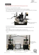
Page 37: ...o Create positioning tool of Rear lens group holder for lens alignment Page 22 15 for how to create Lens alignment equipment for periphery Monitor LINE GENERATOR MEGALIGHT 100 CCD camera Lens optical alignment equipment Caution This adjustment is required when the 4th lens group is removed Screw 4 Holder moving lever Stage Attachment holder of the rear lens group J19127P Create cardboards with whi...

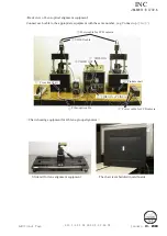
Page 38: ... for 4th lens group alignment Back view of Lens optical alignment equipment VIDEO cable VIDEO IN VIDEO OUT VIDEO IN of LINE A Fiber optic cable Cross line chart Pinhole chart Power cable for CCD camera Power cable for CCD camera Connect each cable to the appropriate equipment with the same number e g Connect up to The chart is embeddied in cardboards INC ...

Page 39: ... the lever Adjust the attachment holder J19127P position by rotating the micrometers for X axis or Y axis so that the center of the attachment holder coincides with that of the rear cover ring of the self made center position ing tool Caution Without this alignment the 4th lens may be damaged by the attachment holder Move the holder moving lever of the alignment equipment upwards and remove the se...

Page 40: ...age on the monitor is like bellow Focus ring Zoom ring Mount the lens on the lens alignment equipment for center Set the focus ring to infinity end Refer to 2 Center positioning of rear lens group holder Page 22 for how to mount the lens Set the Zoom ring to 24 mm Caution Do NOT set the zoom ring to TELE position longer than 24 mm Otherwise the lens will come off from the attachment holder J19127P...

Page 41: ... of the 4th lens unit and loosen the screws Caution When inserting the alignment screwdrivers move the holder moving lever up to lock the holder Then put them straight down in the screw holes so that the screws can be easily found After inserting the alignment screwdrivers unlock the holder moving lever and move the holder down slowly by the lever Rotate the micrometer X axis and Y axis so that th...

Page 42: ...ail tool Focal plane mark of camera Front Back 4 Chart shooting for the rear lens group alignment Prepare a camera D200 Set the shutter speed to M1 60 aperture to full open and the focus mode to S On the shooting menu set Image Quality mode to RAW WB to Preset and ISO to 200 Set the VR mode of the lens to OFF Set up the camera D200 on a tripod on the slide rail Set the indication pointer of the tr...

Page 43: ...ill the entire finder field frame Adjust the tilt of the slide rail to make the three chart lines position in the center of the viewfinder when the tripod is slid all the way to the front and back Turn the power of viewers 5 pcs to ON Caution If the batteries of viewers are exhausted causing decreased brightness the shooting data cannot be obtained correctly Viewer 5 pcs Back Front Connect the PC ...

Page 44: ... front then darken the room Measuring position 7 6 5 4 3 2 1 30cm Focusing position 8cm To front To back If this software is used for the first time the selection screen of reading data will appear This does not appear after the 2nd time usage Select FD_AUTO dll and click Open Click Focusing AF is activated to focus and the shutter is released INC ...

Page 45: ...set to RAW Set the A M change SW to M Slide the tripod to the front by 16 0 1 cm Click Measurement When the shutter of the camera is released slide the tripod to the back by 8 0 1 cm and click Measurement again Repeat this procedure of sliding the tripod in increments of 8 0 1 cm and clicking Measurement at 7 measuring positions The total sliding distance is 48 cm ref Illustration of previous page...

Page 46: ...reen Information display After the seven measurements point the cursor to the confirmation screen of the software Click it three times If Information displays END the lens optical alignment is completed If Information displays other than END go to the next 5 4th lens group alignment Page 22 11 to readjust INC ...

Page 47: ...er Y axis X axis Caution In case the cross lines are tilted adjust them by turning the chart which is screwed in the rear tube of the equipment Cross lines Mount the lens on the equipment for periphery Refer to 2 Center positioning of rear lens group holder Page 22 for how to mount the lens Set the zoom ring to 24 mm Caution Do NOT set the zoom ring to TELE position longer than 24 mm Otherwise the...

Page 48: ...hese X and Y lines X1 knob Y1 knob LINE ON OFF button LINE LOCK button LINE GENERATOR Y line X line Insert the three alignment screwdrivers in the screw holes of the 4th lens unit and loosen the screws Caution When inserting the alignment screwdrivers move the holder moving lever up to lock the holder Then put them straight down in the screw holes so that the screws can be easily found After inser...

Page 49: ...s are rotated but the calibrated cross lines are unable to move do not forcedly rotate them After completing the above shift tighten three screws of the 4th lens unit with the alignment screwdrivers Remove the alignment screwdrivers from the attachment holder J19127P Result values If more accuracy is preferable even if END is displayed adjust by using the value of Outer 1 as the adjustment amount ...

Page 50: ... group alignment Caution After fixing the three screws of the 4th lens unit if the shift amounts are different from the result of the chart shooting repeat the rear lens group alignment until they become equal Turn each power of the monitor LINE GENERATOR and MEGALIGHT 100 to OFF Remove the lens from the equipment for periphery Go back to 4 Chart shooting for the rear lens group alignment Page 22 ...

Page 51: ... JAA80351 Part no 1K631 952 1 Bayonet mount unit JAA80351 Part no 1C999 601 1 For use remove the other components than the bayonet mount section from the bayonet mount unit of RP Screw JAA80351 Part no G1 14035FB 3 3 Procedure Put the bayonet mount as below Mount the rear cover ring on the bayonet mount and fix them with three screws Put with the groove in which the lock pin of camera body enters ...

Page 52: ...actual size of viewers makes it easier to fit the positions of viewers tightly Put the 2nd flattened cardboard box size 2 33 on the above cut out 1st cardboard together as one and fix them by taping at 4 sides Ref Fig 3 Then as for the 2nd flattened cardboard box cut out the shape again by matching the cut out size of for each viewer Ref Fig 4 Reinforce the edges of cut out parts with tape Note To...

Page 53: ...dboard boxes Put the 2nd flattened cardboard boxe on the1st cut out cardboard together as one as shown below Fig 4 As for the 2nd flattened cardboard box cut out the shape in the same way as Fig 2 Cut out by matching the size of the 1st cutting Fig 5 Light viewers are embedded Fig 6 Setting board is blackened with the chart being attached Fix them by taping at 4 sides To prevent viewers falling of...

Page 54: ...upwards 1st lens group side Rubber ring 62 Set the zoom to TELE side Mount the rear cover ring 39 and position it by turning counterclockwise Tighten the screw 91 first then the two screws 91 to fixate the rear cover ring 39 There must not be NO gap between the rear cover ring 39 and the bayonet mount 30 Rear cover ring 39 91 91 91 INC ...

Page 55: ...ing paper of the company name plate 113 Align the index of the zoom ring 52 with the cutout of the company plate 113 and mount 113 Company name plate 113 Cutout Index Peel off the backing paper of the name plate 68 and VR name plate 69 then adhere them Name plate VR name plate 69 68 INC ...

Page 56: ...B is replaced be sure to perform Writing of FLASH ROM fixed elec adj values AF S DX 18 55 VR Inspection and adjustment program J18434 The below hardware requirements are necessary for installing the program on a computer Ensure them before installation PC IBM PC AT compatible OS Windows XP Home Edition Windows XP Professional Windows 2000 CPU Pentium Ⅱ 266MHz Pentium Ⅳ 2GHz RAM Memory 32MB or more...

Page 57: ...tage power supply Set voltage 6V Oscilloscope AF I communication box J15306 1 AF I communication adapter J15307 PC As long as PC is IBM PC AT compatible any CPU type is available If the RS232C terminal of PC is a 9 pin type connect it by using the 25 pin 9 pin conversion connector This connector is NOT supplied as RJ so use commercial products on the market New tool INC ...

Page 58: ...e main menu Follow the instructions on the screen for preparation Then click Next Click Yes if the main PCB is replaced while click No if it is NOT replaced Clicking Yes goes on to Backup of FLASH ROM elec adj values on Page A39 Writing of FLASH ROM fixed elec adj values on Page A45 Adjustment for electrical device Changed page 1 M サービス 計画課 February 10 2008 Revision INC ...

Page 59: ...JAA80351 R 3739 A 28 AF S DX 18 55 3 5 5 6G VR Click Next When the adjustment is completed click Close to end the procedure INC ...

Page 60: ...1 R 3739 A 29 AF S DX 18 55 3 5 5 6G VR Click Inspection of PI encoder operations on the main menu Inspection of PI encoder operations Follow the instructions on the screen for preparation Then click Next INC ...

Page 61: ...le the lens scanning is driven the pulse shows an abnormal value Do NOT touch the zoom ring during operations Standard Total pulses 1920 2148 PULSE S If Inspection result shows Good click Close Set the zoom ring to WIDE end or TELE end and click OK Changed page 1 M サービス 計画課 February 10 2008 Revision INC ...

Page 62: ... 18mm W or 55m T at the following five lens positions Lens position Index position Horizontal lens position Index facing 1 up 2 right 3 left 4 Front lens group 60 angle upward 5 Front lens group 60 angle downward Lens position in inspecting Click Start insp Click Inspection of lens driving stop accuracy on the main menu INC ...

Page 63: ...as the lens does not stop during the inspection of Lens Driving Stop Accuracy any value can be input without problem However the larger the value of Delay time gets the longer the inspection time becomes If the lens stops input a numeric number into Delay time from 0 to 1000 msec so that the lens does NOT stop Tick here when measuring with the front lens group facing 60 angle up downward INC ...

Page 64: ... Error pulse occurrence ratio Judgment Horizontal 0 33 GOOD Horizontal 34 97 GOOD if 40 or less Horizontal 67 97 GOOD if 20 or less 60 0 33 GOOD 60 34 97 GOOD if 40 or less 60 67 97 GOOD if 20 or less Df1 Df6 shows the lens driving amount The number of overrun underrun pulses must be within the following standards after the lens back and forth driving 1 motion INC ...

Page 65: ...ns driving time on the main menu Inspection of lens driving time Make inspections by focal length 18mm W or 55m T at the following five lens positions Lens position Index position Horizontal lens position Index facing 1 up 2 right 3 left 4 Front lens group 60 angle upward 5 Front lens group 60 angle downward Lens position in inspecting INC ...

Page 66: ...in the standard E terminal H terminal E terminal H terminal Driving time Driving time Oscilloscope setting V Div 5V Coupling DC Time Div 20m Sec Trigger Mode SGL S Trigger Coupling DC Trigger Source CH1 There are two types in shape of waveforms of E and H terminals Waveform 1 starts and goes up 2 starts and goes down INC ...

Page 67: ... of Lens switches and Lens conditions Click Inspection of lens switches and lens condition on the main menu If there is no problem with each check item click Close to end the procedure Follow the instructions on the screen for preparation Then click Next INC ...

Page 68: ...AA80351 R 3739 A 37 AF S DX 18 55 3 5 5 6G VR Click Lens firmware version on the main menu Lens firmware version Follow the instructions on the screen for preparation Then click Next Click Read data INC ...

Page 69: ...JAA80351 R 3739 A 38 AF S DX 18 55 3 5 5 6G VR Confirm that there is no mistake in the lens name and firmware version Then click Close to end the procedure INC ...

Page 70: ... VR How to back up Click Backup of FLASH ROM elec adj values on the main menu Backup of FLASH ROM electrical adjustment values Follow the instructions on the screen for preparation Then click Next Click Read of Reading from Writing into lens INC ...

Page 71: ...AA80351 R 3739 A 40 AF S DX 18 55 3 5 5 6G VR When reading FLASH ROM data is completed click OK Click OK e g Type the file name in any folder and click Save Click Save of Loading of Saving into file INC ...

Page 72: ...JAA80351 R 3739 A 41 AF S DX 18 55 3 5 5 6G VR Click Close to end the procedure INC ...

Page 73: ... DX 18 55 3 5 5 6G VR Select the file name in the folder that was saved as backup and click Open button e g Click Load of Loading of Saving into file How to restore Click Backup of FLASH ROM elec adj values on the main menu INC ...

Page 74: ... 5 5 6G VR When writing FLASH ROM data is completed click OK Follow the instructions on the screen for preparation Then click Next Click Write of Reading from writing into lens When reading FLASH ROM data is completed click OK button INC ...

Page 75: ...JAA80351 R 3739 A 44 AF S DX 18 55 3 5 5 6G VR Click Close to end the procedure INC ...

Page 76: ...iting of FLASH ROM fixed electrical adjustment values Click Writing of FLASH ROM fixed elec adj values on the main menu When writing FLASH ROM data is completed click OK button Follow the instructions on the screen for preparation Then click Next INC ...

Page 77: ...to back up Click Backup of FLASH ROM elec adj val and LDATA on the main menu Backup of FLASH ROM electrical adjustment value and LDATA Follow the instructions on the screen for preparation Then click Next Click Read of Reading from Writing into lens INC ...

Page 78: ...AA80351 R 3739 A 47 AF S DX 18 55 3 5 5 6G VR When reading FLASH ROM data is completed click OK Click OK Type the file name in any folder and click Save Click Save of Loading of Saving into file e g INC ...

Page 79: ...JAA80351 R 3739 A 48 AF S DX 18 55 3 5 5 6G VR Click Close to end the procedure INC ...

Page 80: ... DX 18 55 3 5 5 6G VR How to restore Click Backup of FLASH ROM elec adj val and LDATA on the main menu Select the file name in the folder that was saved as backup and click Open Click Load of Loading of Saving into file e g INC ...

Page 81: ...55 3 5 5 6G VR When reading FLASH ROM data is completed click OK When writing FLASH ROM data is completed click OK Follow the instructions on the screen for preparation Then click Next Click Write of Reading from Writing into lens INC ...

Page 82: ...JAA80351 R 3739 A 51 AF S DX 18 55 3 5 5 6G VR Click Close to end the procedure INC ...

Page 83: ...incl inspection of aberration compensation VR adjustment Main PCB unit Adjustment of aberration compensation SWM unit Fixed tube unit VR unit 4th lens group Gyro FPC Necessary adjustment when replacing parts Parts to be replaced Adjustments Changed page 1 M サービス 計画課 February 20 2008 Addition INC ...

Page 84: ...er switch WARNING This equipment uses the laser beam Do not look at the laser beam directly or through the laser beam window SERVO switch VIBRATION switch Notes Keep the approx 5 m distance from the laser beam window to the radiated surface Do not block the light path of the laser beam 2 Connect the PC to the equipment J15380 and start the PC 3 Mount and fixed the lens on the equipment J15380 Set ...

Page 85: ... on the Lens selection screen 6 If the following messages appear follow the instructions on the screen and click OK Note Do not change the lens settings until the adjustment is completed and the screen goes back to the Lens selection screen Otherwise the correct adjustment value cannot be obtained caused by a change of the setting position Changed page Overall revision M サービス 計画課 7 Fix the lens wi...

Page 86: ...ainer stand to the position as shown below and fix it by tightening the clamp J15380 8 Changed page Overall revision M サービス 計画課 Procedure for fixing Lens 1 Attach the adapter J15380 8 to the lens retainer stand and move the lens retainer stand in the direction of the arrow January 10 2008 INC ...

Page 87: ...Execute VR mode switch inspection 2 The position of the VR mode switch is indicated Selecting the VR mode switch indicates the current position 3 When the VR mode switch inspection is completed click Exit to end the procedure VR mode switch Changed page 1 M サービス 計画課 Revision January 10 2008 INC ...

Page 88: ...M polarity adjustment auto control This VCM polarity adjustment auto control detects the polarity of the VCM Voice Coil Motor and writes it in FLASH ROM as the compensation value Caution If NG appears during each adjustment click Next to exit from the inspection mode After updating FLASH ROM go back to the Lens selection screen and make the adjustment again However if NG appears even after adjusti...

Page 89: ...ult is OK click Next 5 When the message window appears confirm that the lens position is 0 angle and click OK Clicking OK starts Hall element driven current adjustment 6 When the message window appears confirm that the lens position is 90 angle and click OK INC ...

Page 90: ...gnetic lock center position adjustment Auto control This electromagnetic lock center position adjustment adjusts the center position in the time of electromagnetic lock 9 If the result is OK click Next Clicking Next starts the after adjustment inspection 10 When the message window appears confirm that the lens position is 0 angle and click OK Clicking OK starts the after adjustment inspection INC ...

Page 91: ...VR 11 When the inspection result is OK click Next 13 When the inspection result is OK click Next 12 When the message window appears confirm that the lens position is 0 angle and click OK Clicking OK starts the electromagnetic lock inspection INC ...

Page 92: ... R 3739 A 61 AF S DX 18 55 3 5 5 6G VR 14 When the message that shows updating FLASH ROM is finished appears click OK 15 When the following message appears turn the VR switch of the lens to OFF and click OK INC ...

Page 93: ... Click Action The laser pointer will move in any of the four directions Confirm the moved direction 1 Loosen the laser switch nut of the VR lens adjustment equipment J15380 and rotate the knob in the direction of the arrow to radiate the laser beam Laser pointer Laser switch knob Viewed from above Nut Changed page 1 M サービス 計画課 March 25 2008 Addition INC ...

Page 94: ...f it does not move towards the direction click No and repeat the procedures from 3 to 7 5 Click the button that corresponds to the moved direction of 3 6 Click OK and confirm that the laser pointer moves towards the upper right direction 4 The laser pointer will move in any of the four directions Confirm the moved direction and click OK Click OK Changed page 3 M サービス 計画課 March 25 2008 Revision Add...

Page 95: ...When the upper right movement is confirmed click Next 10 When the message window appears set Frequency setting of the VR lens adjustment equipment J15380 to 3 0 Hz based on the instructions January 10 2008 M サービス 計画課 Changed page Overall revision INC ...

Page 96: ...t J15380 starts to vibrate measure the vibration width α of the laser beam 13 Click Next on the message window The vibration reduction function starts and the vibration width of the laser beam becomes narrow Notes During the above measurement laser spot light swings from side to side and up and down This phenomenon is caused by operations of the VR unit control so NOT defective Changed page 1 M サー...

Page 97: ...vibration movement stabilizes 14 If the angle is deviated the laser beam source looks like turning around even after making the Gyro gain adjustment So if such deviation is detected adjust and correct it by the adjustment buttons Buttons for adjusting Angle deviation Changed page 1 M サービス 計画課 Revision January 10 2008 INC ...

Page 98: ...ate the center width α and adjustment values refer to the procedure from to on the next page Adjustment value Buttons for adjusting Gyrog Gain Peak zone of the minimum value of the vibration width Standard Center vibration width α One fifth 1 5 1 8 or less of the maximum vibration width Note The laser beam vibrates widely again after passing the peak section of the minimum value Changed page 3 M サ...

Page 99: ...n width can be obtained by the actual measured value The middle of the peak zone is regarded as the adjustment value Gyro Gain Vibration width Adjustment Actual measured Value value 0 90 43 5 mm 0 92 42 5 mm 0 94 41 0 mm 0 96 40 5 mm 0 98 40 0 mm 1 00 40 0 mm 1 02 40 0 mm 1 04 40 5 mm 1 06 41 0 mm 1 08 41 5 mm 1 10 42 0 mm Note Measure the vibration width in increments of 0 5 mm For adjusting the ...

Page 100: ...d by the arrow then press START button of VIBRATION switch of the VR adjustment equipment J15380 to start vibrations 18 At the 90 position adjust the angle deviation and make gyro gain adjustment Note When adjusting the lens at the 90 angle position use the buttons for the adjustment at 90 position as below Buttons for adjustment at 90 position Changed page 1 M サービス 計画課 Revision January 10 2008 IN...

Page 101: ... not recorded and the adjustment details are not written 22 Click Quit on the adjustment items screen to go back to the Lens selection screen 21 When the message window appears switch off the laser and stop the vibration Then click OK Note Do NOT remove the lens or turn OFF the VR lens adjustment equipment until going back to the Lens selection screen Otherwise troubles will occur such as incorrec...

Page 102: ...dge from the controlling sound Cause Checksum defect Broken wire of the VCM Both sides Mode switch defect Others Measure Perform the checksum with the equipment then go to the Check 1 Confirm the breakage of the VCM then go to Check 1 Make the switch inspection with the equipment Go to Check 2 Cause Breakage of the VCM One side Abnormal adjustment value Others Measure Confirm the breakage of the V...

Page 103: ...f the vibration width How much does the vibration width reduce when the VR mode changes from OFF to ON by the VR gyro adjustment Cause Incorrect adjustment value Others Measure Make the lens position adjustment and the VR gyro adjustment The electric parts other than VR may be defective The parts other than VR may be defective More than 1 5 1 5 or less INC ...

Page 104: ... completing inspecting and adjusting the main PCB 1 Preparation Test chart Self made tool ref Procedure for how to create it Tripod D200 D2X PC USB cable UC E4 Adjustment software J18436 LWM_AFS18_55 exe used for the lens optical alignment 2 Procedure for how to create test chart Photocopy the next page and cut out one target chart and five resolution charts 300mm 45mm 45mm 45mm 45mm 56μm 56μm 28μ...

Page 105: ...JAA80351 R 3739 A 74 AF S DX 18 55 3 5 5 6G VR Target chart Resolution chart INC ...

Page 106: ... Exposure mode to A the aperture to full and Focus mode to S On the shooting menu set the Image quality mode to FINE Image size to L WB to Preset and ISO to 200 Set up the camera D200 or D2X to which the suspected lens is attached on the tripod Set the focal length to 55 mm and the distance between the test chart and camera CCD face to 2 m 20 2 cm Set the center of the focus area coming in the tar...

Page 107: ...first time the selection screen of reading data will appear This does not appear after the 2nd time usage Select FD_AUTO dll and click Open Caution Unless the focal length is set to 55 mm or 18 mm the following window will appear and the procedure will be blocked Click Defocus rectify Revision Changed Page 2 M サービス 計画課 Addition January 10 2008 INC ...

Page 108: ...28μ m 0μ m Click JPEG Shot The shutter is released after the AF operation The shot image is automatically displayed on the PC screen Scale the image to 100 and check which chart is in focus of the five resolution charts Caution Because this lens has a deep focal depth even if the aperture is fully open when looking for the center of focus compare two distant charts between which there are two or m...

Page 109: ...the distance between the test chart and camera CCD face to 72 m 2 cm Perform the procedure from of the previous page to Input the value data of the focus position into the entry field e g The following means 28μm front focus side position is in focus Check that the values of all the focal lengths are displayed within the dotted red circle Then click Rewriting Revision Changed Page 3 M サービス 計画課 Jan...

Page 110: ...ocedure starts and ends the below screen will appear Click OK to end the adjustment software Turn the camera OFF and turn it ON again Then reboot the adjustment software Note Unless the camera turns off once the value that was written in Flash ROM is not reflected Revision Changed Page 1 M サービス 計画課 January 15 2008 INC ...

Page 111: ...DE side shooting at the procedure of and then to take TELE side shooting at the procedure of If 0μm position is not in focus repeat the procedure from to If it is not still in focus even after repetition the written value in Flash ROM may be abnormal So click Design value Rewriting to write the initial value then proceed with the procedure Revision Changed Page 1 M サービス 計画課 January 15 2008 INC ...

Page 112: ...705 0 5MMX500G 工具設定なし RJNo is not available パーソナルコンピュータ PERSONAL COMPUTER 工具設定なし RJNo is not available オシロスコープ OSCILLOSCOP J18434 AF S DX 18 55 3 5 5 6G VR 点検 調整ソフト Adj SOFT for AF S DX 18 55 3 5 5 6G VR J18435 VR調整ソフト VR Adj SOFT for AF S DX 18 55 3 5 5 6G VR J18436 調芯装置用調整ソフト LWM Adj SOFT LWM for AF S DX 18 55 3 5 5 6G VR J18004 1 J18004用基準ゲージ STANDARD GAUGE FOR J18004 J15306 1 AF I通信ボックス AF I L...

Page 113: ...30MEL OIL BARRIER PL 22SEL ドライサ フ PL 22SEL DRY SERF PL 22SEL OIL BARRIER MZ 800SEL ドライサ フ MZ 800SEL DRY SERF MZ 800SEL OIL BARRIER I 40 AFレンズ用グリ ス I 40 GREASE FOR AF LENS EDB0011 ネジロック 赤 1401C SCREW LOCK 1401C L 241 ロックタイト 241 青 LOCTITE 241 50ml SX720B セメダイン SX720B 黒 CEMEDINE SX720B BLACK TA 0012 ポリエステル フィルム Polyester Film J5033 導電マット CONDUCTIVE MAT J5033 5 リストストラップ WRIST STRAP INC ...

Reviews: