JAA63051-R.3689.A
- A30 ・ AF-S VR MC 105/2.8G -
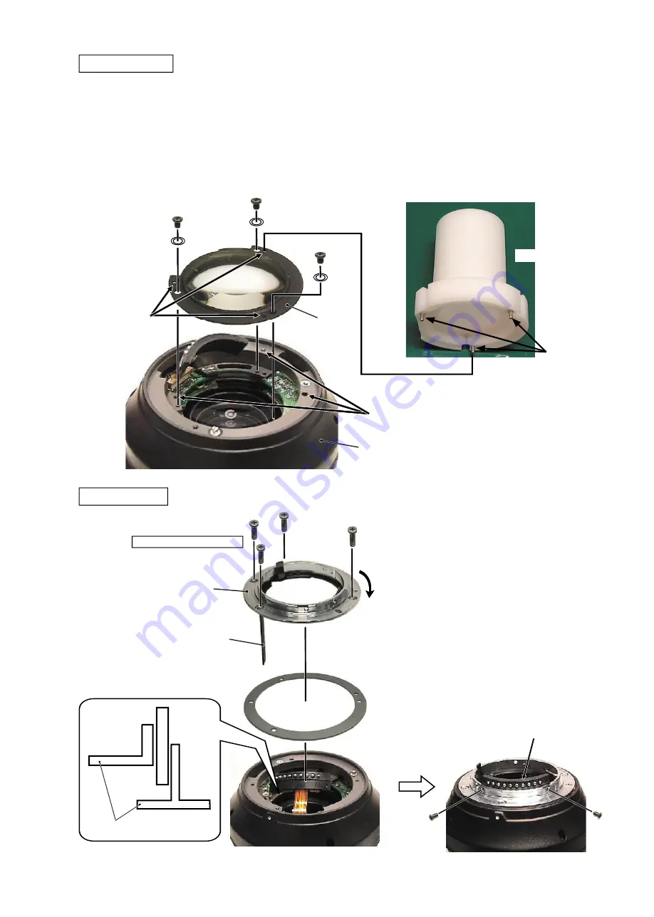
①
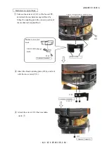
Align the three pins of the 5th lens-G assembling tool (
★
J11325) with the three holes of the 5th lens-G unit,
and mount the tool on the lens body.
②
Align the three holes of the lens body with the three pins of the tool, and assemble them. Then fi x them with
the three washers (#151) and the three screws (#113).
③
Remove the tool from the lens body.
Caution:
Tighten the
three screws
(#113) in the
order from
①
to
③
.
★:
New tool
#113×3
#151×3
★
J11325
Pin×3
Hole×3
5th lens-G
Lens body
①
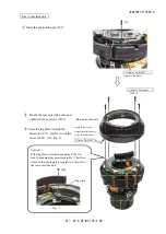
Fit position of the holes of the washer
(#176), and mount it.
②
Insert the aperture lever (#109) of the
bayonet mount into the aperture unit
by fi tting in the bending part of the
aperture unit.
③
Fix the bayonet mount with four
screws (#136).
④
Fix the contact unit with the two
screws (#66).
Bayonet mount
①
②
③
Contact unit
#66×2
Bayonet mount
#176A
~
M
#136×4
Aperture unit
#109
#109
Direction for
positioning
Adhesive: Lockend B
Apply to the three screws (#136) except "A".
Hole×3
A
5th lens group
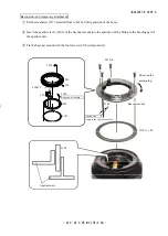
Caution:
Removing the 5
th
lens group needs the lens alignment work after the assembly.
Therefore, at service facilities where the lens alignment cannot be performed, do NOT remove the 5
th
lens
group.
Summary of Contents for AF-S VR Micro Nikkor 105mm/f2.8G
Page 13: ...JAA63051 R 3689 A D11 AF S VR MC 105 2 8G Focus index unit 83 3 GMR unit Focus index unit ...
Page 100: ...JAA63051 R 3689 A A76 AF S VR MC 105 2 8G Target chart Resolution chart ...
Page 107: ...JAA63051 R 3689 A F1 AF S VR MC 105 2 8G 外観図 Sketch drawings ...
Page 108: ...JAA63051 R 3689 A F2 AF S VR MC 105 2 8G 組立図 Structure of the Lens ...
Page 109: ...JAA63051 R 3689 A F3 AF S VR MC 105 2 8G ...
Page 110: ...JAA63051 R 3689 A F4 AF S VR MC 105 2 8G ...
Page 111: ...JAA63051 R 3689 A F5 AF S VR MC 105 2 8G ...
Page 112: ...JAA63051 R 3689 A F6 AF S VR MC 105 2 8G ...
Page 113: ...JAA63051 R 3689 A F7 AF S VR MC 105 2 8G ...

